background image


EVAL-ADP5588


Rev. 0 | Page 7 of 20 

2.


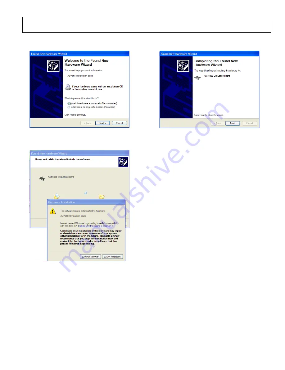
The screen in Figure 20 then appears. Choose 

Install the 

software automatically (Recommended)

 and click 

Next >

0

81

02-

021


Figure 20. Software Location Installation  

3.


When the screen in Figure 21 appears, click 

Continue 

Anyway

; this completes the USB driver installation. 

08

102

-02

2


Figure 21. Windows Compatibility Warning  


4.


When the screen in Figure 22 appears, click 

Finish

 to 

complete the USB driver installation. 

0

810

2-

02

3


Figure 22. USB Driver Installation Completion 

USING THE SOFTWARE 

Before running the software, make sure that the ADP5588 
board assembly is plugged into the USB port. When it is 
plugged in properly, the two supply LEDs (D19 and D21)  
light up. Then click 

START>All Programs>Analog Devices> 

ADP5588Evaluation Software

.


The software then detects the presence of the board USB 
interface and prints the message 

Firmware Downloaded okay


at the bottom left side of the screen (see Figure 23). If USB 
communication is not established, a 

Firmware not Downloaded 

USB Communication Error

 prints instead. If the latter message 

appears, unplug the board and try it again. 

THE APPLICATION TABS  

The ADP5588 software application has four tabs: the 

Keypad


application tab, the 

GPIOs

 configuration tab, the 

Light-Sensors


configuration tab, and the 

History

 tab. The 

History

 tab allows 

you to record a sequence of commands that can be converted into 
scripts later on. This is useful during software development.  

Register Programming 

To program a particular register, click the pertinent SIM LED or 
tab on the left side of the menu and select the appropriate value. 
When finished, click 

Program 0xXX 

to program the register 

(XX represents the register address to be programmed). When 
programmed, the value in the register can be read by clicking 

Read 0xXX 

(XX represents the register address to be read).  

The interrupt status registers, keypad status registers, and input 
values can be read the same way. 


Содержание ADP5588

Страница 1: ...he hardware necessary to power the IC and establish USB communication with the PC Two 20 pin connectors J11 and J12 are used to plug in the daughterboard The ADP5588 IC is mounted on the daughterboard...

Страница 2: ...tion Board Assembly 3 Software Installation 4 ADP5588 Evaluation Installation 4 LabVIEW Runtime Engine Installation 5 USB Driver Installation 6 Using the Software 7 The Application Tabs 7 Schematics 1...

Страница 3: ...EVAL ADP5588 Rev 0 Page 3 of 20 DEMONSTRATION BOARD ASSEMBLY 08102 002 Figure 2 Daughterboard 08102 003 Figure 3 Motherboard...

Страница 4: ...rs click Next to continue with installation 08102 007 Figure 4 ADP5588 Evaluation Software Setup 2 When the screen in Figure 5 appears click Yes to accept the license agreement 08102 005 Figure 7 Setu...

Страница 5: ...OK to continue 08102 010 Figure 10 LabVIEW WinZip Self Extractor 2 When the screen in Figure 11 appears click Unzip to extract the files 08102 011 Figure 11 LabVIEW Unzipped Files 3 When the screen in...

Страница 6: ...be restarted to complete installation 08102 019 Figure 18 Restart Screen USB DRIVER INSTALLATION When the GUI and LabVIEW Runtime Engine are installed assemble the daughterboard onto the motherboard...

Страница 7: ...ware Downloaded okay at the bottom left side of the screen see Figure 23 If USB communication is not established a Firmware not Downloaded USB Communication Error prints instead If the latter message...

Страница 8: ...the unused GPIOs can be used for other functions other functions include GPIs GPOs and light sensor comparator inputs 2 Enable KE interrupt for key presses and releases if needed by setting Bit 0 in...

Страница 9: ...interrupt triggering is needed set the GPIO interrupt enable bit for the rows and columns in Register 0x1A Register 0x1B and Register 0x1C 4 Define the trigger level for any of the rows or columns fo...

Страница 10: ...0x1F 2 Set the bit for the row or column that needs to be configured as a GPO in Register 0x23 Register 0x24 and Register 0x25 3 Set the drive level for the GPO lines in Register 0x17 Register 0x18 an...

Страница 11: ...it 0 and Bit 1 in Register 0x1F 2 Set Bit 0 and or Bit 1 in Register 0x30 to enable Comparator 1 and or Comparator 2 3 Set Bit 2 and or Bit 3 of Register 0x30 to enable interrupt for the comparators i...

Страница 12: ...n command sequences are recorded the list of commands can be saved as a script file and later used as input to program all of the registers for a particular configuration or setting The script file al...

Страница 13: ...e LK1 LK2 C19 and C20 as closed to U2 as possible 1 2 LK3 1 Way Link LK3 1 Way Link C1 1UF 16V C1 1UF 16V 1 3 5 7 9 11 13 15 17 19 2 4 6 8 10 12 14 16 18 20 J2 J2 1 2 LK2 1 Way Link LK2 1 Way Link 1 2...

Страница 14: ...EVAL ADP5588 Rev 0 Page 14 of 20 08102 029 Figure 28 Daughterboard Layout Top Layer 08102 030 Figure 29 Daughterboard Layout Bottom Layer...

Страница 15: ...0 0k R3 8 1 0 0k R3 1 1 0 0k R3 1 1 0 0k R59 6 80 R59 6 80 4 5 6 1 2 3 J5 J5 2 1 3 SW3 SW3 2 1 3 SW14 SW14 C34 0 1 uF C34 0 1 uF 3 4 2 1 S40 S40 IN 1 1 S 1 3 D 1 2 IN 2 1 6 IN 3 9 IN 4 8 D 2 1 5 S 2...

Страница 16: ...9 11 13 15 17 19 2 4 6 8 10 12 14 16 18 20 J11 J11 C24 2 2uF C24 2 2uF D13 APDS 9005 D13 APDS 9005 R15 680 R15 680 D19 LED D19 LED A0 A1 A2 VSS SDA SCL WP VCC U8 M24C64 R U8 M24C64 R R17 100k R17 100k...

Страница 17: ...H3 39 I3 40 J3 Row4 41 A4 42 B4 43 C4 44 D4 45 E4 46 F4 47 G4 48 H4 49 I4 50 J4 Row5 51 A5 52 B5 53 C5 54 D5 55 E5 56 F5 57 G5 58 H5 59 I5 60 J5 Row6 61 A6 62 B6 63 C6 64 D6 65 E6 66 F6 67 G6 68 H6 6...

Страница 18: ...EVAL ADP5588 Rev 0 Page 18 of 20 08102 033 Figure 33 Motherboard Layout Bottom Layer...

Страница 19: ...On Inc LTW 170TK 8 2 D12 D13 Photo sensor Avago Technologies APDS 9005 9 1 JP1 USB connector Hirose Electric UX60 MB 5ST 10 18 J1 to J8 J13 to J22 3 2 connector Sullins Connector Solutions PEC36DAAN...

Страница 20: ...GUIDE ESD CAUTION Model Temperature Range ADP5588 EVALZ1 Evaluation Board 1 Z RoHS Compliant Part 2009 Analog Devices Inc All rights reserved Trademarks and registered trademarks are the property of...

Отзывы: