Rev 13 May 2013 17:57 | Page 5
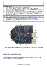
Jumper Description
J202
This jumper selects between internal V
REF
and external V
REF
.
To choose the internal 1 V reference, connect Pin 3 (DUT_SENSE) to Pin 5 (GND).
To use the on-board
1 V reference, connect Pin 2 (DUT_SENSE) to Pin 1 (AVDD), and
connect Pin 4 (DUT_VREF) to Pin 6 (EXT_REF).
To apply a reference voltage from an external off-board source, connect Pin 2 (DUT_SENSE)
to Pin 1 (AVDD) and apply the reference voltage to Pin 4 (DUT_VREF). The AD9653 can
accommodate reference voltages from 1.0 V to 1.3 V; the AD9253 and AD9633 reference
voltage is specified to be 1.0 V.
J204
Use this jumper to power down the ADC. Using the SPI, the PDWN pin can be configured to
be STBY (standby).
J302
This jumper sets the ADC for SPI communications with the
.
Connect Pin 1 to Pin 2 for SDIO, Pin 4 to Pin 5 for SCLK, and Pin 8 to Pin 9 for CSB.
J803
This jumper enables the on-board crystal oscillator.
Figure 2. Default Jumper Connections for
Board
Evaluation Board Circuitry
This section explains the default and optional settings or modes allowed on the
,

