UG-1698
Rev. 0 | Page 17 of 23
A comprehensive
user guide is available on the Analog
Devices, Inc., website. For any general information relating to
the
tool, refer to the
user guide on the Analog
Devices website at
https://wiki.analog.com/resources/tools-
A typical
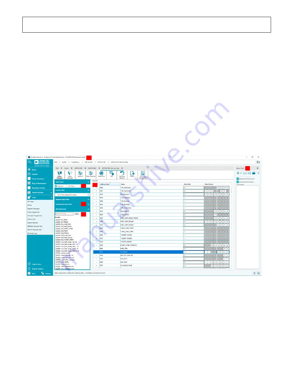
software window is shown in Figure 18. In this
view, various tabs that allow control of the evaluation board
hardware are shown below the red Label 1. The user can click
each tab to navigate to the various windows.
In the
Select View
area (Label 2), the user can choose the
memory map view as
Registers
or
Bit Fields
.
In the
Registers
view (Label 4), the full registers are shown.
Some registers can be expanded to show the bit field names and
descriptions that the user can view.
In the
Bit Fields
view, the bit fields are listed alphabetically and
have widgets to control them and set bits, whereas in the
Registers
view, the control is by bit or hexadecimal word. Both
views can program the registers and are based on user
preference.
Because the
has a large register map, the
Functional
Groups Filter
view (Label 3) allows the user to reduce the
number of registers to view at a time.
By selecting this group and expanding the registers, the user can
quickly find the registers and update their values. Click the
Apply
Selected
or
Apply Changes
button above the
Select View
section (Label 2
)
after a register is changed to program the
change to the device.
To open the
Macro Tools
section on the right (Label 5), select
Macro Tools
from the
Tools
dropdown menu to the left of the
window. The
Macro Tools
section lists the macros that are
currently open in the session. The user can click the name of
the desired macro to make it active in the screen. Click the
Play
button (right pointing triangle) to play the selected macro.
The user can use
Search
Bit Fields
(Label 6) to find a bit field.
22
324
-0
19
1
4
2
3
6
5
Figure 18. Functional Group View of the AD9166 in


