Anaheim Automation DPE25601 Скачать руководство пользователя страница 10

August 2012

L010199

10

Methods of Communication

There are two methods for sending commands to the DPE25601.  One is to directly talk to the 

DPE25601 by using Direct Talk Mode.  This is usually used with a computer or PLC (Programmable 

Logic Controller), where the computer or PLC gives the DPE25601 serial commands to off-load its 

processor.  For example: A PLC can utilize its outputs to toggle the DPE25601’s inputs and gain con-

trol of variable speeds, variable programs, variable distances, etc.  Simply using the DPE25601 as 

the intelligent pulse generator, a PLC can remove some of the tasks that were not meant for ladder 

logic or any PLC processing time.

The second way to give commands to the DPE25601 is to use the software program SMC60WIN to 

either manually control, or to write and send programs.  This method is used when the DPE25601 

is the main controller.  For example: A DPE25601 can replace simple motion control and replace I/O 

functional when minimal quantities of I/O are required to control specific machinery.  Simple motion 

profiles that can operate with 6 or less inputs and 8 or less outputs can utilize a DPE25601 controller.
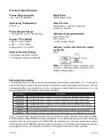
Baud Rate

A term used frequently is serial data communications, a “baud” is defined as the reciprocal of the 

shortest pulse duration in a data word signal, including start, stop, and parity bits.  This is often taken 

to mean the same as “bits per second”, a term that expresses only the number of “data” bits per 

second.  Very often, the parity bit is included as an information or data bit.  

The DPE25601 accepts 

a baud rate of 38400 only

.

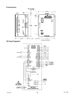
RS232 Protocol - Controller SW1 in RS232 Position

The DPE25601 is a DCE device, therefore it will transmit on pin 2 and receive on pin 3 of the DB9 

RS-232 connector.  The RS232 serial communication mode is single ended.  This means that for each 

signal there is one wire, and a common ground reference used by all the signals.  The DPE25601 

does not use handshaking, thus the CTS and RTS lines are internally connected, and the CD, DTR 

and DSR lines are internally connected inside the DPE25601.  The signal line maintains levels of 

+5VDC to +15VDC and -5VDC to -15VDC.  For a valid logic level in the controller, the voltage must 

be at least +/- 3 volts.  RS232 works at distances of up to 50 feet maximum.

 RS232 is susceptible 

to electrical noise, and should not be used in noisy areas.  Always use the shortest cable con

-

nection possible.  NOTE: Keep Controller wiring separated from motor cable/wiring.

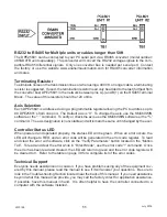
RS485 Protocol - Controller SW1 in RS485 Position

The RS485 protocol mode is as follows; On board receivers will remain in active mode indefinitely.  Trans

-

mitters must be turned off when the unit is not sending data, to prevent the line from sending and receiving 

data at the same time.  Therefore when the PC is transmitting data its driver will be turned on and each 

of the units connected will have their drivers off.  If they are requested to send data back to the PC, the 

selected unit will turn it’s driver on to send the data and then turn it off after it has completed transmission. 

Note: 

The above protocol is done internally between the converter and the DPE25601.  The RS485 method 

of communication allows increased noise immunity and increased communication distance of up to 4000 

feet without repeaters.  RS485 repeaters allow an additional 4000 feet per repeater.  The DPE25601 is 

designed for two wire configuration.  The 2 wire configuration makes use of the tristate capabilities of RS485 

to allow a single pair of wires to share transmit and receive signals for half duplex communications.  This 

“two wire” configuration (note that an additional ground conductor must be used) reduces cabling cost.  

Note: Keep control wiring separated from motor cable/wiring.

Section 3: Controller Functions

July 2018

Содержание DPE25601

Страница 1: ...E25601 Programmable Driver Pack User s Guide 4985 E Landon Drive Anaheim CA 92807 e mail info anaheimautomation com 714 992 6990 fax 714 992 0471 website www anaheimautomation com A N A H E I M A U T...

Страница 2: ...Motor 9 Section 3 Controller Functions 10 Methods of Communication 10 Baud Rate 10 RS232 Protocol Controller SW1 in RS232 Position 10 RS485 Protocol Controller SW1 in RS485 Position 10 Axis Selection...

Страница 3: ...otors in a bipolar fashion The DPE25601 s driver features motor current ON OFF capabilities and a Reduced Current Enabled to automatically reduce motor current to 50 of the set value after the last st...

Страница 4: ...t Anaheim Automation Inc or its representatives for information on the latest releases Part Number Description DPE25601 Controller Drive Pack Features a 2 5 amp bipolar drive and 24W power supply DPY5...

Страница 5: ...August 2012 L010199 5 Dimensions Wiring Diagrams July 2018...

Страница 6: ...it Switch Inputs 1 Home Limit 2 Jog 3 Jog 4 Fast Jog 5 Hard Limit 6 Hard Limit 7 Soft Limit 8 Soft Limit 9 Ground Position Description Motor Connection 1 Input 1 Analog Input 2 Input 2 Index on the fl...

Страница 7: ...elow Anaheim Automation offers a comprehensive line of step motors in 14 17 23 34 and 42 frame sizes Contact the factory to verify motor compatibility with the DPE25601 Section 2 Step Motor Current Se...

Страница 8: ...ves The specified motor current which is the unipolar value is multiplied by a factor of 1 0 1 4 or 2 0 depending on the motor configuration series half coil or parallel Step Motor Configurations Step...

Страница 9: ...current rating by 2 0 to determine the current setting potentiometer value Note After the current has been determined according to the motor connections above use Table 3 to choose the proper setting...

Страница 10: ...le ended This means that for each signal there is one wire and a common ground reference used by all the signals The DPE25601 does not use handshaking thus the CTS and RTS lines are internally connect...

Страница 11: ...k the axis use the SMC60WIN software or the command The axis designation is nonvolatile and will remain the same until changed by the user Controller Status LED When powered and operated properly the...

Страница 12: ...ese limits are directional NOTE Whenever a soft limit switch is activated the motor will decelerate and run at base speed during an indexing move or stop during a slewing move Be sure to come back pas...

Страница 13: ...n analog voltage to either set the absolute position of the motor or to set the maximum speed of the motor The set the position when told via the go to analog position command the input will read a vo...

Страница 14: ...specified number of mil liseconds Range 1 to 65535 If Then Statements The if then statements are conditional based on the values preset in the program The user can either test each individual input o...

Страница 15: ...on Deceleration The acceleration and deceleration are the same value The acceleration is entered directly as steps sec2 and controls the time that the motor will take to move from base speed to max sp...

Страница 16: ...dows 7 Windows 95 98 NT ME 2000 XP Installation Option 1 1 Insert the CD into the drive 2 From the Program Manager select Start Run 3 Enter D setup and click OK use the appropriate drive letter i e D...

Страница 17: ...xis Set axis selection and stored axis of the controller Select Axis Sets the axis select parameter in the SMC60WIN software 1 99 Define Axis Sets the programmable address in the controller 1 99 New P...

Страница 18: ...top Program Stop the execution of the program in the controller memory View Program View the program stored in the controller memory Clear Program Memory Clear the program memory in the controller Aut...

Страница 19: ...rmat www anaheimautomation com Opens up the Anaheim Automation Website About Displays the verison of the SMC60WIN and contact information The Unit is Connected The Unit is Not Connected On the right o...

Страница 20: ...top the program and all motion from running Connect Establish communication with the controller Tab Sheets Real Time Motion Monitor and control motion of the controller Encoder Options and Registratio...

Страница 21: ...longer triggered One switch is required to stop anti backlash Home using Soft and Home Switches Motor will seek the home position by moving towards home switch but motor will slow down to base speed...

Страница 22: ...t position to set the output to the controller Set of Steps Between Outputs Send of steps to take between activated outputs to the controller Set of Output Counts Send of output counts to the controll...

Страница 23: ...Lower Limit Send the analog position lower limit to the controller Set Position Upper Limit Send the analog position upper limit to the controller Set Analog Position Motor will move to position based...

Страница 24: ...ected line of code Insert Insert a new line of code before the currently selected line of code Delete Deletes the currently selected line of code Tab Sheets Create and Edit Program DPE25601 Memory Ava...

Страница 25: ...I O routines Goto For Loop Encoder and Thumbwheel Commands Software section that allows user to manipulate branching and loop routines enter encoder parameters and control the thumbwheel switches Anal...

Страница 26: ...ter in the controller Finish Move Command will allow any motion command to be completed before continuing to the next line of code This command should be used after every motion command Repeat Last Mo...

Страница 27: ...iven value If the inputs do not match the next line is skipped If input matches then ex ecute the next line otherwise skip the next line This conditional command allows the user to execute the next li...

Страница 28: ...he thumbwheel position for the thumbwheel to be enabled Move Thumbwheel Index Relative move command will allow motor to move the defined number of steps set by the thumbwheel switches Encoder Auto Cor...

Страница 29: ...osition lower limit to the value specified Analog Position Upper Limit Sets the analog position upper limit to the value specified Output on the Fly On Off Sets the output on the fly feature on or off...

Страница 30: ...tion per second RPS PPS Convert from revolution per second to pulses per second Steps Per Rev Enter the number of steps per revolution of the step motor The default is for a 200 step rev motor in half...

Страница 31: ...ers if characters are to be echoed back to the screen Instructions All instructions require that no spaces be sent between the command and the parameter followed by a carriage return 0 not 0 correct 0...

Страница 32: ...set this value to 0 This command is used in conjunction with the output on the fly enabled command Range 0 65535 D 1st Output on the Fly Position Format D value Description This command sets the posi...

Страница 33: ...e mo tor ratio is 1000 4 400 10 This command is used in conjunction with the encoder auto correct EA command Range 1 255 ER Encoder Retries Format ER value Description This is the number of times the...

Страница 34: ...nge directions and run at base speed unit the release of the home limit input The ramp profile is specified by the B base speed M max speed andA acceleration deceleration commands I Read Inputs Format...

Страница 35: ...d It is also used to set the registration index during and index on the fly move Motion is not activated by this command it only sets the index register Range 0 8388607 Format 2 N Description This com...

Страница 36: ...g position the analog position lower limit and the analog position lower limit commands S Go Slew Format S Description This command will send clocks out to the DPE25601 The only commands that can stop...

Страница 37: ...iption Command Description A Verify acceleration decerlation O Verify outputs B Verify base speed T Verify motor current 1 is on 0 is off C Verify Steps between outputs on the fly Z Verify position D...

Страница 38: ...use a 0 This command is used in conjunction with the number of steps between outputs C 1st output position D and number of outputs commands Clockwise Format Description This command sets the direction...

Страница 39: ...tion This command will either enable or disable input 1 to be used to set the ana log speed To enable the function use a 1 To disable the function use a 0 This command is used in conjunction with the...

Страница 40: ...nalog position input This command is used in conjunction with the analog position enable and absolute position P commands Range 0 65535 Analog Position Upper Limit Format value Description This comman...

Страница 41: ...er 8 If problems still exist contact Anaheim Automation Tech Support Problem There is no power to the DPE25601 controller Possible Solutions 1 Is the DPE25601 controller connected to the appropriate p...

Страница 42: ...Please make sure that the base speed is less than the max speed and that the speeds are within their valid ranges 32 Range Overflow Error The go to position has an overflow error This is caused by the...

Страница 43: ...ion 7 Sample Programs Sample Program 1 Sample Program 1 illustrates a typical application where a system moves to a specific position required The sample program shows how to use motion and go to inst...

Страница 44: ...m 2 illustrates a typical application where a system is first sent home to a datum or 0 position This sample program shows how a motor will move to a 3 different positions utilizing some of the motion...

Страница 45: ...r input 1 to be a value of 0 grounded and then is indexed 10 000 steps During this index output 1 needs to be turned on every 1000 steps 5 times starting at position 2000 At the end of the index outpu...

Страница 46: ...t used and input 1 is masked high due to analog function being used The third step is to slew using the analog input as the maximum speed between 5000 and 10000 steps revolution When input 2 is switch...

Страница 47: ...humbwheel switch that is connected to each unit for indexing The direction is then set for Axis 0 and Axis 1 and these two axes are then told to index the distance set in each thumbwheel at the same t...

Страница 48: ...ns Versions 1 00 Initial Release Versions 1 10 Fixes lockup on RS485 Communication Added capability to stop the motor on an Encoder Error after the Encoder Retries number has been reached Version 2 00...

Страница 49: ...aheim Automation products in life support applications assumes all risks of such use and indemnifies Anaheim Automation against all damages LIMITED WARRANTY AllAnaheimAutomation products are warranted...

Отзывы: