


28
Using the Wall-Mounted Door Control
THE MULTI-FUNCTION DOOR CONTROL
Press the push button to open or close
the door. Press again to reverse the door
during the closing cycle or to stop the
door while it's opening.
Light feature:
Press the Light button to turn the opener
light on or off. It will not control the opener lights when
the door is in motion. If you turn it on and then activate the
opener, the light will remain on for 4-1/2 minutes. Press
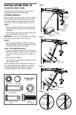
again to turn it off sooner. The 4-1/2 minute interval can be
changed to 1-1/2, 2-1/2, or 3-1/2 minutes as follows: Press
and hold the Lock button until the light blinks (about 10
seconds). A single blink indicates that the timer is reset to
1-1/2 minutes. Repeat the procedure and the light will blink
twice, resetting the timer to 2-1/2 minutes. Repeat again
for a 3-1/2 minute interval, etc., up to a maximum of four
blinks and 4-1/2 minutes.
Lock feature:
Designed to prevent operation of the door
from hand-held remote controls. However, the door will
open and close from the Door Control, the Outside Keylock
and the Keyless Entry Accessories.
To activate, press and hold the Lock button for 2 seconds.
The push bar light will fl ash as long as the Lock feature is
on.
To turn off, press and hold the Lock button again for 2
seconds. The push bar light will stop fl ashing. The Lock
feature will also turn off whenever the “learn” button on the
motor unit panel is activated.
To Open the Door Manually
NOTICE: To comply with FCC and or Industry Canada (IC) rules,
adjustment or modifications of this receiver and/or transmitter are
prohibited, except for changing the code setting or replacing the
battery. THERE ARE NO OTHER USER SERVICEABLE PARTS.
Tested to Comply with FCC Standards FOR HOME OR OFFICE USE.
Operation is subject to the following two conditions: (1) this device may
not cause harmful interference, and (2) this device must accept any
interference received, including interference that may cause undesired
operation.
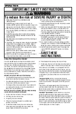
To prevent possible SERIOUS INJURY or DEATH:
• NEVER allow small children near batteries.
• If battery is swallowed, immediately notify doctor.
To reduce risk of fi re, explosion or chemical burn:
• Replace ONLY with 3V2032 coin batteries.
• DO NOT recharge, disassemble, heat above 100° C
(212° F) or incinerate.
To prevent possible SERIOUS INJURY or DEATH from a
falling garage door:
• If possible, use emergency release handle to disengage
trolley ONLY when garage door is CLOSED. Weak or
broken springs or unbalanced door could result in an
open door falling rapidly and/or unexpectedly.
• NEVER use emergency release handle unless garage
doorway is clear of persons and obstructions.
• NEVER use handle to pull door open or closed. If rope
knot becomes untied, you could fall.
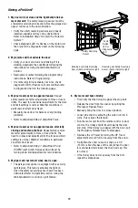
Care of Your Opener
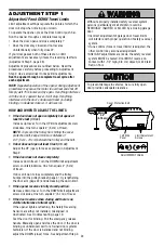
LIMIT AND FORCE ADJUSTMENTS:
Weather conditions may cause some
minor changes in door operation
requiring some re-adjustments,
particularly during the fi rst year of
operation.
Pages 24 and 25 refer to the limit and force adjustments.
Only a screwdriver is required. Follow the instructions
carefully.
Repeat the safety reverse test (Adjustment Step 3,
page 26) after any adjustment of limits or force.
MAINTENANCE SCHEDULE
Every Month
• Manually operate door. If it is unbalanced or binding,
call a trained door systems technician.
• Check to be sure door opens and closes fully. Adjust
limits and/or force if necessary (see pages 24 and 25).
• Repeat the safety reverse test. Make any necessary
adjustments (see Adjustment Step 3).
Two Times a Year
• Check chain tension. Disconnect trolley fi rst. Adjust if
necessary (see page 7).
Every Year
• Oil door rollers, bearings and hinges. The opener does
not require additional lubrication. Do not grease the
door tracks.
Every Three to Four Years
• Use a rag to wipe away the existing grease from the
garage door opener rail. Reapply a small layer of white
lithium grease to the rail.
THE REMOTE CONTROL BATTERY
The lithium battery should
produce power for up to 5 years.
To replace battery, use the visor
clip or screwdriver blade to pry
open the case as shown. Insert
battery positive side up (+).
Dispose of old battery properly.
Replace the batteries with only
3V2032 coin cell batteries.
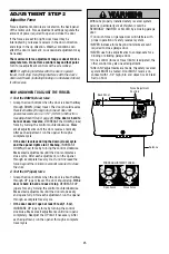
FORCE CONTROLS
LIMIT CONTROLS
Push
Button
Lock
Button
Light
Button
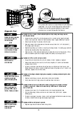
MANUAL DISCONNECT
POSITION
Trolley
Release
Arm
Emergency
Release
Handle
(Pull Down)
LOCKOUT POSITION
Trolley
Release
Arm
Emergency
Release
Handle
(Down and Back)
The door should be fully closed
if possible. Pull down on the
emergency release handle and lift the
door manually. To reconnect the door
to the opener, press the door control
push bar.
The
lockout feature
prevents
the trolley from reconnecting
automatically. Pull the emergency
release handle down and back
(toward the opener). The door can
then be raised and lowered manually
as often as necessary. To disengage
the lockout feature, pull the handle
straight down. The trolley will
reconnect on the next UP or DOWN
operation, either manually or by using
the door control or remote.


