


3
Creating and downloading a sample audio signal source:
Step 1.
Every time AD2 starts up a small window will appear asking which Anadigm chip to use. Look at
the small lettering in the center of the space above the square design area window which should say
AN221E04. If yes then select the
Continue with default chip
button and proceed. If some other
part number shows then select the
Choose a different chip
button and change to AN221E04.
Step 2.
Point to the pull down menu under
Settings
and select
Preferences
. The Chip Type should be
AN221E04 as established above. Select the
Port
tab and then activate the
Select Port
pull down
option arrow to show the available options. In general,
COM1
is the best choice but this is PC
dependent. Select
COM1
for now, select the
Apply
button and then
OK
. If Step 3 below does not
work then select another COM port option and try Step 3 again. Be sure the serial cable is secure.
Step 3.
Start AD2 and select
Target > Display Board Information
. A window will appear with the PAM
software version and the part number of the Anadigm IC used (AN221E04). Click
OK
.
Step 4.
Select
Edit > Insert New CAM
. CAM means “Configurable Analog Module” which is the AD2
name for the pre-defined analog functions. The index to the library of CAMs will be displayed. Point
to and double click the Sinewave Oscillator CAM which will appear attached to the tip of the cursor.
Drag it into the AD2 design area and click once to drop it.
Step 5.
The parameter set up window specific to this CAM will appear. Click
OK
to accept defaults.
Step 6.
Select
Settings > Active Chip Settings > Clocks
to adjust the system clock parameters. Point to
Clock 1
setting and use the LEFT/RIGHT slider to set this clock to be divided by
400
times from the
system clock frequency to be
40.0 kHz
. Leave all other clock settings unchanged and click
OK
.
Step 7.
Point to the Sinewave Oscillator CAM icon, right click and select
CAM Settings
. Set the parameters
as follows to achieve
440 Hz
(
0.44 kHz
) oscillator output:
•
Point to
Clock A
and use the pull down option arrow to select
Clock 1
(at
40 kHz)
•
Point to the
Osc. Frequency
value window (temporarily red), enter
0.44
and then
OK
•
Point to the
Peak Amplitude
value window to confirm
3.6 Volts
(default) and then
OK
.
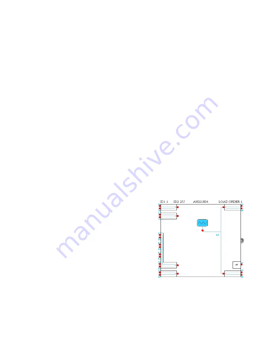
Step 8.
Point to the red output port below the Sinewave
Oscillator CAM icon and watch the wiring tool
pointer appear. Drag the pointer to the upper right
output port and release to set the wire. Point to any
place along the new blue wire just installed to start a
new wire branching off of this wire. Drag the
pointer to the lower right output port and release to
set the wire. There should now be connections
between the output port of the Sinewave Oscillator
and the two output ports of the Anadigm IC. The
wire just created is labeled “
n1
”.
Step 9.
Point to the
Download
icon (it has a blue downward pointing arrow). Click once to download the
configuration file representing this design into the Anadigm IC on the PAM. The PAM should show
three green LEDs as ON with the 440 Hz Tuning-A tone coming out of the speakers. The green LED
next to DIP2 socket indicates that a correct Anadigm configuration download has been completed
and the analog signal processing is running.
Step 10.
The voltage output waveforms can be observed at the terminal posts labeled OUT1 and OUT2.


