AMX Corporation reserves the right to alter specifications without notice at any time.
For full warranty information, refer to the AMX Instruction Manual(s) associated with your Product(s).
036-004-2682 4/05 ©2005
AMX Corporation. All rights reserved. The AMX logo is a trademark of AMX Corporation. AMX reserves the right to alter specifications without notice at any time.
3000 RESEARCH DRIVE, RICHARDSON, TX 75082 • 800.222.0193 • fax 469.624.7153 • technical support 800.932.6993 • www.amx.com
93-2252
REV: H
RJ-45 Connections
Use a standard CAT5 Ethernet cable to provide communication between
the touch panel, NXA-AVB, and the NetLinx Master.
Ethernet 10/100 Base-T Connector
The Ethernet cable (connected to the rear of the Table Top Panels or to
the side of the Wall Panel) provides 10/100 network connectivity between
the panel and the NetLinx Master.
Modero Setup and System Connection
1.
Carefully remove the panel from the shipping box, peel the protective
plastic cover from the LCD and apply power to the panel.
2.
From below the LCD, press the grey Front Setup Access button for 6
seconds (passing-over the Setup page) to access the Calibration
setup page and follow the on-screen instructions.
3.
Press the grey Firmware Setup Access button for 3 seconds to open
the Setup page and touch the on-screen
Protected Setup
button.
4.
Enter the panel password into the keypad. Factory default is
1988
.
5.
Press the
Device Number
field to open the on-screen Device
Number keypad and enter a value for the panel (
default is 10001
).
6.
Press
Done
when finished and press the on-screen
Reboot
button
to cycle power to the panel.
7.
Repeat step 3 to access the Protected Setup page and touch the
System Connection
button to open the System Connection page
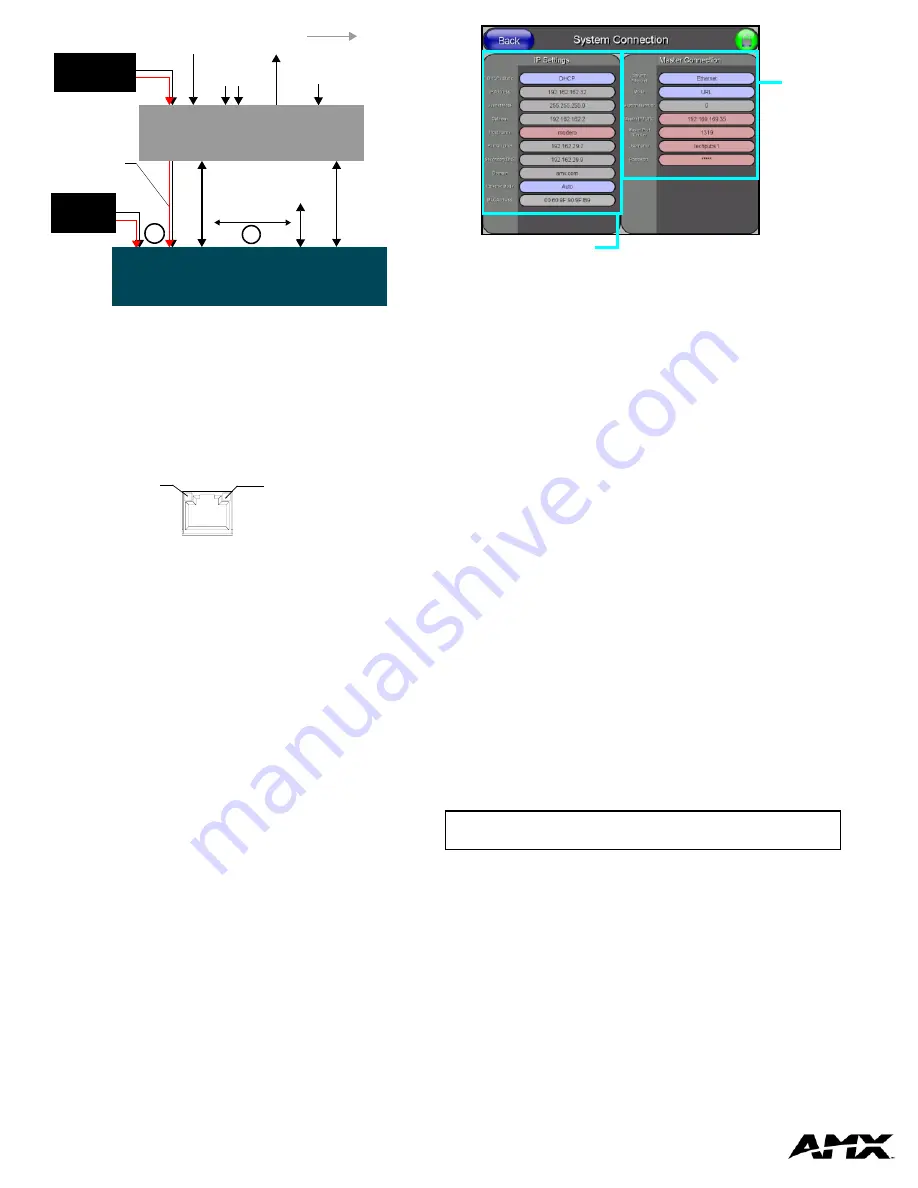
(FIG. 6).
Setting up the System Connection Parameters
There are two choices for communication with the system Master:
Ethernet
or
ICSNet. The default method used for Master connection is
Ethernet
.
First - Setup the Master Connection
To configure Ethernet communication:
1.
Under the Master Connection column, toggle the
ICSNET/Ethernet
field until the choices cycle to
Ethernet
.
2.
Press the
Mode
button:
•
URL
- In this mode, enter the System Number (zero for an unknown
System Number) and the IP/URL of the Master (Master Port Number
is defaulted to
1319
).
•
Listen
- In this mode, add the Modero’s IP Address into the URL List
of the Master (using NetLinx Studio). This mode sets the Modero
panel to "listen" for broadcasts from the Master (using the panel IP
from its URL list).
•
Auto
- In this mode, enter the System Number of the NetLinx Master.
This mode instructs the
Modero to search for a Master that uses the
same System Number (assigned within the Master Connection
section) and that
resides on the same Subnet
.
To configure ICSNet Communication:
1.
Under the
Master Connection
column, toggle the
ICSNET/Ethernet
field until the choices cycle to
ICSNET
.
2.
All other settings are disabled and do not apply.
Second - Setup the IP Settings (Panel Communication)
Toggle the on-screen
DHCP/Static
field to select the appropriate setting
for your system.
•
DHCP
- With this setting, other settings are greyed-out and do not
apply. Typically the Host Name can be left blank. These fields
(“pulled” from the Ethernet connection) are filled-in by the panel after
the unit is rebooted.
•
Static IP
- With this setting, you must enter the network information
as provided by your Network Administrator.
Remaining System Connection Parameters
1.
Set the speed of the Ethernet connection to the panel by selecting
from either: Auto (
default
), 10 Half Duplex, 10 Full Duplex, 100 Half
Duplex, or 100 Full Duplex.
2.
Enter a valid username and/or password (
if the target Master is
secured
).
3.
Press the
Back
button and then press the on-screen
Reboot
button
to save the changes and cycle power.
NOTE: Press the on-screen Reboot button after any changes are
made to the touch panel’s Communication Parameters.
Setting up a Modero Wireless Connection
Refer to the
12"
and
15" Modero Touch Panel Series
Instruction Manual
for detailed wireless connectivity setup and configuration information.
FIG. 4
Sample Wiring configuration on CV Modero Panels
FIG. 5
Layout of Ethernet LEDs
NXD/T-CV12/15
ICSNet In
PSN power
(RJ-45)
Video In
(BNC)
Mic Out
(4-pin captive-wire)
Audio In
(6-pin captive-wire)
NXA-AVB
PSN4.4/PSN6.5
supplied via
NXA-AVB box
ICSNet
(CAT5)
Audio/Video
(CAT5)
Line Level out
(to amplifier
or VOL card)
Touch Panels
or
Direct
Connect
Breakout Box
Ethernet
(front)
(rear)
or
(CAT5)
supply
PSN power
supply
A
- Activity LED
when receiving Ethernet
data packets.
(yellow) blinks
L
- Link LED (green) blinks
when the Ethernet cables
are connected and
terminated correctly.
FIG. 6
Sample System Connection page
Panel’s connection information
Master’s
connection
information


