

Installation Guide
MAX-AVM Audio Video Module
MAX-AVM Audio Video Module
The MAX-AVM Audio Video Module (FIG. 1) is a streaming DVD/music playback
module that works in conjunction with the MAX MMS MultiMedia Servers.
The AVM provides A/V output in two formats: VGA and S-Video, and features both
analog stereo and coax digital audio outputs.
•
MMS servers communicate via Ethernet to up to 25 MAX-AVM audio/video
modules.
•
Multiple AVMs require a Gigabit Ethernet switch (not included) as indicated in
Product Specifications
Installation Procedures
The procedure for installing the MAX-AVM is outlined below, and the steps are
described in the following sections:
1.
Install the AVM Setup Serial Number (indicated on a decal on the bottom panel
of the AVM) in the MMS server.
2.
Connect the AVM to an MMS server and a display device.
Installing the MAX-AVM Serial Number In the MMS Server
AVMs utilize the system software loaded in the MMS server to boot. In order for the
AVM(s) in the system to be recognized by the MMS server, they must each be added
to the system. Use the
Server Configuration
options in WinMAX to add AVMs to the
MMS server:
1.
Open the
System Information
tab in WinMAX, and click on the
Server
Configuration
button to access the MAX Admin menu
.
2.
Go to
Output Module Setup > Add Output Module > AVM
to access the
Enter
Output Number
dialog.
3.
In the
Enter Output Number
field, enter an available server output/zone number
(
range = 1 - 33
). This is the output number that will appear in WinMAX. Click OK
to proceed.
Note
: The server will not allow you to assign an audio output to an output/zone
that is already in use. To determine which server outputs are already being used,
select
View
from the Output Module Setup menu.
•
If other output modules (AOM or AVM) have already been added to the server,
then assign the AVM to the next available output.
•
Note that AVMs take only one output on the MMS server.
4.
In the
Enter Serial Number
field, enter the setup serial number of the AVM you
are adding to the system in the text box. The serial number is printed on a decal
located on the underside of each AVM enclosure.
5.
The system will notify you that the module has been added to the system. Click
OK
to return to the Output Module Setup menu.
Once the module has been added, select
View
from the Output Module Setup menu.
The module you just added should appear in the list of Installed Output Modules. AVM
modules are listed by MMS output /zone number assignment, serial number and IP
address.
Select
Remove
to remove an existing output module from the system.
Connecting the MAX-AVM to an MMS Server and Display Device
Note
: Be sure to power up the MMS server
before
applying power to the MAX-AVM.
1.
Connect audio outputs using one of the two output options:
a) Use the supplied audio adapter (mini-stereo to RCA) for analog audio output.
b) Use a coaxial cable for digital audio output.
2.
Use either a VGA or S-Video cable to connect to the video output on the AVM to
the display device.
3.
Use an Ethernet cable to connect the AVM’s Ethernet port to a Gigabit Ethernet
switch.
4.
Use an Ethernet cable to connect the Gigabit switch to the A/V OUT connector
on the MMS server.
5.
Connect the included power supply.
6.
Turn on the power button (front panel) and allow up to one minute for the AVM to
boot up.
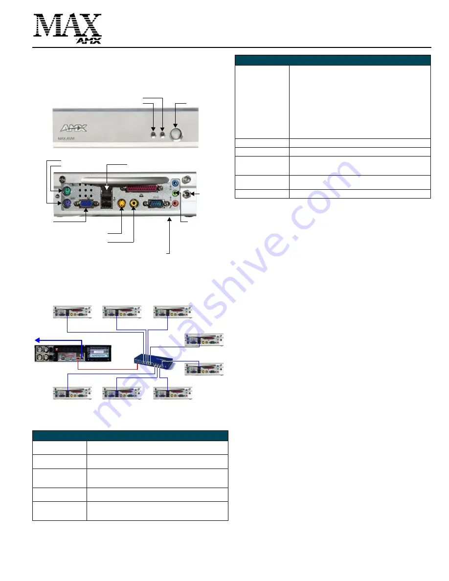
FIG. 1
MAX-AVM Audio Video Module (front view)
FIG. 2
Example installation using multiple MAX-AVMs
MAX-AVM (FG 2178-50) Specifications
Power:
• 12VDC 5A external power supply (included)
• 110-240 VAC 50/60 Hz
AC Current Draw (AMP):
• .47A - Bootup/Power Cycle Peak
• .41A - Normal Usage Peak
Video Output:
• VGA video output: 1024 x 768 resolution @60 Hz.
• S-Video output: NTSC/PAL
• Aspect Ratio control: selectable 16:9 (wide screen) or 4:3.
Audio Output:
• Digital: 6-channel Dolby digital and DTS
• Analog: Stereo
Front Panel Components:
• Blue Power LED
• Blue hard drive activity LED (not used)
• Power button
Ethernet (from MMS Server)
RCA (coax)
S-Video Out
VGA out
Audio Line Out
Power
Connector
Mouse port
Keyboard port
digital audio out
(for use with the
included RCA
Y-adapter for
Setup Serial Number is printed on a decal on the bottom panel
Power LED
Hard Drive Activity LED
Power button
(front)
(rear)
analog stereo
output)
MMS-12S Server
MAX-AVM
MAX-AVM
MAX-AVM
MAX-AVM
MAX-AVM
A/V OUT (GB)
10/100
MAX-AVM
MAX-AVM
MAX-AVM
10/100
10/100
10/100
10/100
10/100
10/100
10/100
Gigabit
Ethernet
Switch
ETHERNET
CONTROL (GB)
MAX-AVM Specifications (Cont.)
Rear Panel Connectors:
• 1/4” DC power connector.
• PS/2 Keyboard and Mouse ports: for direct control of the AVM.
• RS-232 port: 9-pin (DB-9) Serial port (not used).
• Ethernet port: RJ-45 Ethernet port provides 10/100 network
connectivity between the AVM and the MMS server.
• USB ports (not used)
.
• S-Video Out: Mini-Din4 port provides composite S-video monitor
output.
• Parallel port (not used)
.
• VGA out: DB15HD port provides VGA output.
• Audio Line Out: 1/8” stereo analog audio output (for use with the
included RCA Y-adapter).
• Line In/Mic In (not used).
• RCA (coax): S/PDIF digital audio output.
Dimensions (HWD):
• 2 3/16” x 7” x 11” (5.56 cm x 17.78 cm x 27.94 cm)
Weight:
• 6.50lbs (2.95 kg)
Operating Environment:
• Operating Temperature: 50° to 95° F (10º to 35º C)
• Operating Relative Humidity: 20% to 80% (non-condensing)
• Minimum Ventilation Clearance: 1" (on all sides)
Included Accessories:
• 12VDC 5A external power supply
• 1/8” stereo to RCA (female) Y adapter
Certification:
FCC, CE