For full warranty information, refer to the AMX Instruction Manual(s) associated with your Product(s).
7/08
©2008 AMX. All rights reserved. AMX and the AMX logo are registered trademarks of AMX.
AMX reserves the right to alter specifications without notice at any time.
3000 RESEARCH DRIVE, RICHARDSON, TX 75082 • 800.222.0193 • fax 469.624.7153 • technical support 800.932.6993 • www.amx.com
93-1110-03
REV: B
Tuner 1 Jumper Settings
The Tuner Module installed in position 1 must be set to Tuner 1, as shown in FIG. 7:
Tuner 2 Jumper Settings
The Tuner Module installed in position 2 must be set to Tuner 2, as shown in FIG. 8:
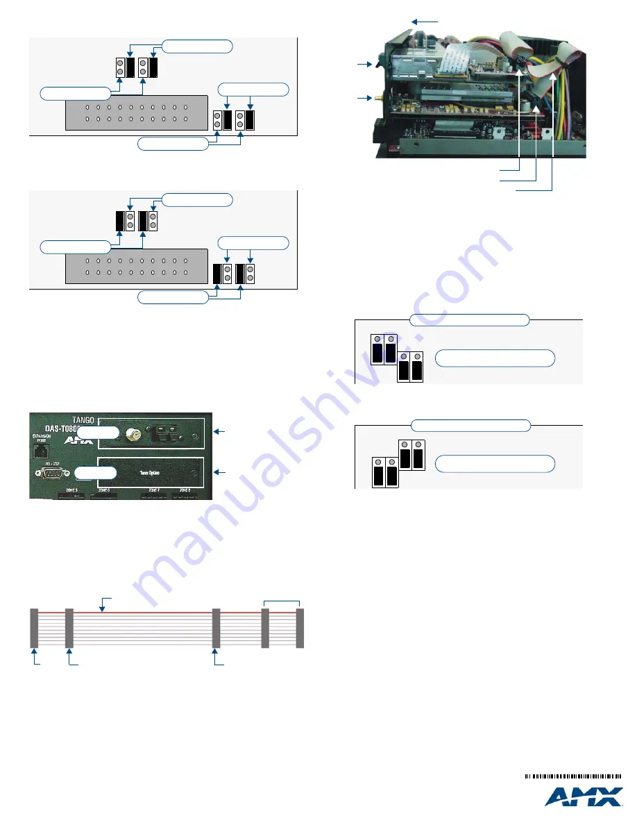
Installing the DAS-SIRIUS Tuner Module
Since Mi-Series and Tango Audio Controllers are shipped with a DAS-AMFM Tuner Module
pre-installed in the
Tuner 1
position (on the rear panel of the Controller - see FIG. 9), the
DAS-SIRIUS Tuner Module, is typically installed in position #2 (labeled
Tuner Option
).
Installing the DAS-SIRIUS Module Into Position 2
To install the DAS-SIRIUS Tuner Module into the Position 2 Tuner slot:
1.
Remove the cover from the Audio Controller.
2.
Remove the
Tuner Option
cover plate on the rear panel (FIG. 9) to expose the Posi-
tion 2 mounting slot for the Tuner Module.
3.
Carefully insert the DAS-SIRIUS Tuner Module into the Controller, with the
electronics facing up, and replace the cover plate screws to secure the Module to the
Controller.
Note
: Be careful not to damage the white ribbon cable on the top of the Tuner Mod-
ule.
•
The
Rear Panel
connector at the end of the Tuner Ribbon Cable is connected to the
Controller’s rear board pin-bus (see FIG. 2).
•
Keep the Tuner Ribbon Cable oriented so that the red stripe is always on top, as indi-
cated in FIG. 10:
4.
Connect the
Tuner 2
connector on the ribbon cable to the 20-pin Tuner Ribbon Cable
connector on the DAS-SIRIUS Module (FIG. 11).
•
Keep the Tuner Ribbon Cable oriented so that the red stripe is always on top, as indi-
cated in FIG. 10.
•
Verify that all of the 20-pin connectors of the Tuner Ribbon Cable are securely
plugged into their respective boards.
5.
The Controller should only be powered back on once all Tuners are installed.
Removing Tuner Modules
In some cases it is necessary to remove the existing Tuner Module, in order to install a
different Tuner Module. Since each Tuner Module uses 1 source input on the Audio
Controller, you may choose to use the source input for other purposes.
1.
Remove the cover from the Audio Controller.
2.
Carefully remove the ribbon cable from the Tuner Module.
3.
Remove the screws from the Tuner Module cover plate (on the Controller’s rear
panel) and carefully slide the Tuner Module out of the chassis.
4.
To remove TUNER 1, place the TUNER 1 Audio Controller jumpers in the OFF
position (FIG. 12).
5.
To remove TUNER 2, place the TUNER 2 Audio Controller jumpers in the OFF
position (FIG. 13).
6.
To remove both Tuner Modules, set all Audio Controller jumpers in the OFF position.
Connecting and Positioning the SIRIUS Antenna
1.
Connect the provided SIRIUS Antenna to the DAS-SIRIUS (see FIG. 1).
2.
Verify the Signal strength
a. Access the programming menus via the front of the Controller.
b. Select Setup\SIRIUS.
c. Select "Status".
d. Select "SAT" to determine the Satellite Signal Strength. Ensure the signal
strength is at a minimum of "weak". Adjustments may need to be made to the
position of the Antenna in order to get a better signal.
Activating Your SIRIUS Subscription
SIRIUS Satellite Radio is a subscription service. In order to use your DAS-SIRIUS module,
you will have to activate your SIRIUS subscription.
Note
: Until you have activated your subscription, you will only be able to tune to channels
0 and 184.
1.
Once you have installed the DAS-SIRIUS module, you can activate your SIRIUS sub-
scription by phone: Call 1.888.539.SIRIUS (7474).
2.
You will be asked for a “Sirius ID”. This ID can be found in several places:
•
If using a Matrix LCD keypad, select channel "0" to display the Sirius ID.
•
If using either a Metreau or Matrix tactile keypad with the optional numeric keypad,
select channel "0". The Sirius ID will be displayed on the LCD display on the front of
the Controller.
•
If using either a Metreau or Matrix tactile keypad without the optional numeric key-
pad, access the programming menus via the front of the Controller by pressing the
centre Nav button on the Controller: Select Setup\SIRIUS, then select "ID" from the
SIRIUS menu, and the SIRIUS ID will be displayed.
For more information, refer to the
DAS-SIRIUS SIRIUS Tuner Module Operation/Reference
Guide
(available at www.amx.com).
FIG. 7
Tuner Module - Tuner 1 Jumper Configuration
FIG. 8
Tuner Module - Tuner 2 Jumper Configuration
FIG. 9
Rear Panel Tuner with Tuner Option cover plate
FIG. 10
Tuner Ribbon Cable
TUNER 1 Jumpers
TUNER 1 Jumpers
TUNER 2 Jumpers
TUNER 2 Jumpers
TUNER 1 Jumpers
TUNER 1 Jumpers
TUNER 2 Jumpers
TUNER 2 Jumpers
Position 1
Position 2
(DAS-AMFM installed)
(Tuner Option
cover plate)
TUNER 1
TUNER 2
Tuner 2
Tuner 1
Rear Panel
RED STRIPE (
to Pin 1
)
not used
FIG. 11
Tuner 1 / 2 Module Connections (side view of Controller)
FIG. 12
Audio Controller Jumper Configuration (No TUNER 1)
FIG. 13
Audio Controller Jumper Configuration (No TUNER 1)
rear of Controller (side view,)
DAS-AMFM
DAS-SIRIUS
Tuner 1
connector (to DAS-AMFM Module)
Tuner 2
connector (to DAS-SIRIUS Module)
Tuner Ribbon Cable
Tuner 1 jumpers (in
OFF
position)
Top Left of Rear-Board Pin Bus
3
1
3
1
TUNER 1
Jumpers
Tuner 2 jumpers (in
OFF
position)
Top Left of Rear-Board Pin Bus
3
1
3
1
TUNER 2
Jumpers