background image

User Manual - CTC-1402

29

Web UI Control

The Web UI designed for the CTC-1402 allows basic controls and advanced settings of the device. The Web UI page can be accessed 

through NetLinx Studio.

Access the Web Interface

To get access to Web UI:

1. 

Connect your PC and the LAN port of the CTC-1402 to the same local area network.

2. 

In NetLinx Studio’s Online Tree, select “Web Control Page” > “Launch Web Control Page via NetLinx Studio” (or select “Launch 

Web Control Page via Default Browser”). Entering the IP address in the web page will also enter the web interface.

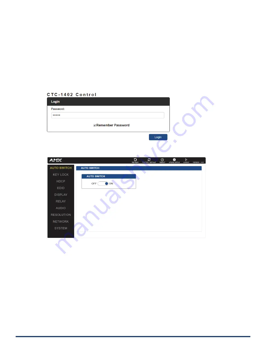
The following page will pop up. Enter the default password “admin” and click “Login”.

After logging in, the following interface appears:

Содержание CTC-1402

Страница 1: ...USER MANUAL VERSION V1 0 0 CTC 1402 Connectivity and Transport Kit Conferencing A V FOR AN IT WORLD ...

Страница 2: ...ock or fire The exclamation point within an equilateral triangle is intended to alert the user to the presence of important operating and maintenance servicing instructions in the literature accompanying the product The lightning flash with arrowhead symbol within an equilateral triangle is intended to alert the user to the presence of uninsulated dangerous voltage within the product s enclosure t...

Страница 3: ...ubject to the following two conditions 1 This device may not cause harmful interference and 2 this device must accept any interference received including interference that may cause undesired operation NOTE This equipment has been tested and found to comply with the limits for a Class A digital device pursuant to part 15 of the FCC Rules These limits are designed to provide reasonable protection a...

Страница 4: ...ormation 15 RS232 15 RELAY 15 Audio Out 16 Installation 17 Wiring 18 OSD 19 Input Source Switching 20 Auto Switching 20 Manual Switching 20 USB Control 21 NetLinx Studio Control 24 Device Number and Ports 24 Send Commands to Control a Device 26 Telnet Control via NetLinx Studio 26 Web UI Control 28 Web UI Control 29 Access the Web Interface 29 Web Interface Introduction 30 Refresh 30 Factory Defau...

Страница 5: ...o Volume 34 Resolution 34 Network 35 System 36 ICSP Parameter 36 Login Password 36 TELNET SSH Access 37 TELNET Account 37 SSH Account 37 Firmware Upgrade 38 Before Starting 38 Transferring KIT Files 38 Troubleshooting 40 API Command Set 41 NetLinx Commands 42 Telnet SSH Commands 50 ...

Страница 6: ...4 8bit HDMI In Out Supports HDMI 2 0 and HDCP 2 2 Provides a variety of interfaces including USB C to simplify meeting room devices management Supports USB hosts like Desktop and Laptop USB devices like keyboard MIC Speaker Camera Whiteboard for conference systems Automatically detects active inputs when sources are connected or there is a source signal change Ethernet can be imported from either ...

Страница 7: ...Hz 4 3 VIC 3 720 x 480p 59 94 60 Hz 16 9 VIC 4 1280 x 720p 59 94 60 Hz 16 9 VIC 5 1920 x 1080i 59 94 60 Hz 16 9 VIC 6 720 1440 x 480i 59 94 60 Hz 4 3 VIC 7 720 1440 x 480i 59 94 60 Hz 16 9 VIC 14 1440 x 480p 59 94 60 Hz 4 3 VIC 15 1440 x 480p 59 94 60 Hz 16 9 VIC 16 Native 1920 x 1080p 59 94 60 Hz 16 9 VIC 17 720 x 576p 50 Hz 4 3 VIC 18 720 x 576p 50 Hz 16 9 VIC 19 1280 x 720p 50 Hz 16 9 VIC 20 19...

Страница 8: ...ver Technical Input 1 x HDBT IN 2 x HDMI IN Input Signal Type HDMI with 4k 60Hz with Chroma sub sampling 4 4 4 8bit HDBT 2 0 Resolution Support VESA 800x6008 1024x7688 1280x7688 1280x8008 1280x9608 1280x10248 1360x7688 1366x7688 1400x10508 1440x9008 1600x9008 1600x12008 1680x10508 1920x10808 1920x12008 SMPTE 1280x7206 8 1920x1080P6 7 8 3840x21602 3 5 6 8 4096x21602 3 5 8 1 at 23 98 Hz 2 at 24 Hz 3...

Страница 9: ...ischarge 0 97kg 2 14lb 5kV Contact discharge CE FCC ETL PSE RCM Certification CE FCC ETL PSE RCM Transmission Distance Note Straight through category cables wired to T568B standard recommended Cable Type Range Supported Video HDMI Input Output 15m 50ft 1080p 60Hz 24bpp Input Output 10m 33ft 4K 30Hz 4 4 4 Input Output 5m 16ft 4K 60Hz 4 4 4 Shielded Cat 6a 7 100m 330ft 1080p 60Hz 80m 262 ft 4K 30Hz ...

Страница 10: ...w the input has signal but is not selected Red the input has no signal but is selected Off the input has no signal and is not selected 5 3 HDMI 3 HDMI TX Button Press to select the HDMI IN 3 TX as input LED LED is located on the left of the button Green the input has signal and is selected Yellow the input has signal but is not selected Red the input has no signal but is selected Off the input has...

Страница 11: ...displays off LED Blue LED is located on the top of the button Blinking 1 time Short Press the button LED extinguishes after finishing the operation Blinking 3 times Hold press the button for 3 seconds LED extinguishes after finishing the operation 10 Relay 1 Relay 1 Button Press to set the screen closed LED Green LED is located on the top of the button Short press the button LED blinks 1 time and ...

Страница 12: ...re to its factory defaults 8 12V Connect to DC 12V power adapter provided 9 DEVICE Connect to USB devices 10 RS232 P Connect an RS232 device to RS232 P of TX and a device to RS232 P of RX for RS232 pass through 11 Host 1 Connect to a PC which is followed with VGA IN1 and DP IN2 When the source is selected the USB devices on TX and RX can be connected to a host PC 12 RS232 C Connect to an RS232 sla...

Страница 13: ... is selected Off the input has no signal and is not selected 5 HDMI 2 HDMI 2 Button Press to select RX HDMI IN 2 source as input LED LED is located on the top of the button Green the input has signal and is selected Yellow the input has signal but is not selected Red the input has no signal but is selected Off the input has no signal and is not selected 6 Display Display control Button Short press...

Страница 14: ...onnect to the provided DC 12V power adapter 8 DEVICE Connect to USB devices 9 Host 1 Connect to a PC which is followed with HDMI IN1 when the source is selected The USB devices on TX and RX can be connected to a host PC 10 Host 2 Connect to a PC which is followed with HDMI IN2 when the source is selected The USB devices on TX and RX can be connected to host a PC 11 RS232 P Connect an RS232 device ...

Страница 15: ...gures show the pinouts of the Phoenix Connectors RS232 Connects to an RS232 enabled device with the 3 pole 3 5mm captive screw connectors Wire as shown below RELAY Connects to a projector screen with the 3 pole 3 5mm captive screw connectors Wire as shown below ...

Страница 16: ...User Manual CTC 1402 16 Audio Out Connect to an audio system such as an amplifier with the 3 pole 3 5mm captive screw connector Wire as shown below ...

Страница 17: ...tion bracket to the enclosure using the screws provided The bracket height can be adjusted Up Down The bracket can face up or down 2 The bracket is attached to the enclosure as shown 3 Repeat steps 1 2 for the other side of the unit 4 Attach the brackets to a surface or suitable location with user supplied screws 5 Repeat steps 1 4 to install the receiver ...

Страница 18: ...ion 4 Connect USB HOST devices Connect a PC to USB HOST ports with USB cables 5 Connect USB devices to the USB DEVICE ports of TX and RX Note For more information refer to USB Control section USB C is automatically recognized when the USB C input is selected The PC can be connected to other USB devices directly 6 Connections additional control options 1 IR Plug the IR emitter into the IR OUT port ...

Страница 19: ...convey its IP address Follow these steps to initiate OSD 1 Hold and Press the HDMI 1 and HDMI 2 buttons on the front panel of RX for at least 3 seconds 2 The IP address of the CTC 1402 will display on the upper right of the connected display s screen for 15s and then disappear ...

Страница 20: ... and the front panel button Power off protection When Auto Switching or Manual Switching are selected before powering off the device will remain in the same mode after powering back on When Auto Switching is selected before powering off and the previously selected port has active signal after powering the device back on the port will remain selected If the port is not active and more than one inpu...

Страница 21: ...e connected to the host PC Please refer to the following diagrams Note USB C is built into USB 2 0 so when the USB C input is selected the PC can be connected directly to other USB devices 1 VGA DP source on TX is selected VGA IN 1 AUDIO IN 1 and HOST 1 are in a group DP IN 2 and HOST 1 is in a group Only if the VGA or DP is selected the USB devices can be connected to the PC which is connected to...

Страница 22: ...he USB C input is selected the USB devices can be connected to the PC directly 4 HDMI IN 1 on RX is selected RX HDMI IN 1 and RX HOST 1 are in a group Only if the RX HDMI IN1 is selected the USB devices can be connected to the PC which is connected to RX USB HOST 1 ...

Страница 23: ...ces can be connected to the PC which is connected to RX USB HOST 2 The CTC 1402 kit supports 1 external USB Hub connected to either the TX or RX Device Port Devices which present themselves as USB hub such as AMX Acendo Vibe will count as 1 external USB Hub USB Device Ports support power to connected devices not to exceed 5A per USB device port ...

Страница 24: ...ws Transmitter Port 1 RS 232 P Port 2 RS 232 C Port 4 IR RX Port 5 USB Device Port 6 DP IN 2 Port 7 VGA IN 1 Audio IN 1 Port 8 HDMI IN 3 Port 9 USB C IN 4 Port 10 USB Host 1 Port 11 USB Host 2 Receiver Port 21 RS 232 P Port 22 RS 232 C Port 24 IR IN Port 25 USB Device Port 26 HDMI OUT Audio Out P Auto Out de embedding Port 27 HDMI IN 1 Port 28 HDMI IN 2 Port 30 USB Host 1 Port 31 USB Host 2 Port 1...

Страница 25: ...User Manual CTC 1402 25 After configuring each port respectively control commands can be sent to the device ...

Страница 26: ...e textbox and click Send To Device For API commands see the Section API Command Set Telnet Control via NetLinx Studio 1 Choose the device you want to control right click then choose TELNET Window Launch TELNET window via NetLinx Studio enter the Telnet window input the Telnet API in this window to control the device Note For API Commands see the section API Command Set ...

Страница 27: ... If Launch TELNET Window via User Defined Program is selected it may be require to enable Telnet as follows 1 Go to Start Control Panel Programs and Features 2 On the left select Turn Windows features On or Off 3 Select the check boxes Telnet Client and Telnet Server and click OK ...

Страница 28: ...User Manual CTC 1402 28 Web UI Control Choose the device to be controlled right click then choose Web Control Page Launch Web Control Page via Default Browser enter the Web UI Control Page ...

Страница 29: ...1 Connect your PC and the LAN port of the CTC 1402 to the same local area network 2 In NetLinx Studio s Online Tree select Web Control Page Launch Web Control Page via NetLinx Studio or select Launch Web Control Page via Default Browser Entering the IP address in the web page will also enter the web interface The following page will pop up Enter the default password admin and click Login After log...

Страница 30: ...top of the interface includes REFRESH FACTORY DEFAULT REBOOT UPGRADE STATUS and Firmware VERSION Refresh Click to refresh the status of device in the Web UI interface Factory Default Click to set the device to factory default Click the button a window pops up Click OK to take effect Reboot Click to reboot the device Click the button a window pops up Click OK to take effect ...

Страница 31: ...ON is the default For more information refer to the Input Source Switching section When set to OFF switching the source can only be Manual Key Lock In this column users can set the key lock On Off ON The panel buttons are disabled for switching the sources and displays OFF The panel buttons are active for switching the sources and displays HDCP In this column users can Enable Disable the HDCP of T...

Страница 32: ...an select the RS232 control mode CONTROL Slide the button to select RS232 control mode Local default Local sending of commands to control the projector Netlinx Sending commands via NetLinx studio to control the projector DEVICE When Netlinx is selected click the down arrow to select TX or RX for RS232 setting BAUD RATE Click the down arrow to select the baud rate PARTY BITS Click the down arrow to...

Страница 33: ... are able to set Relay On Off and the Relay Mode Latch or Momentary RELAY CONTROLLER Click to raise the projector screen and click to drop the projector screen down Latch Level triggered Momentary Pulse triggered The delay time can be set 1 10 seconds ...

Страница 34: ...ge of the audio volume Mute Click to mute the audio Resolution In this column users are able to set Output resolution AUTO or MANUAL AUTO is default AUTO Output resolution is automatically set MANUAL Click to set the output resolution to Manual mode In Manual mode click the down arrow to select a specific output resolution as required APPLY Click to set the output resolution to the desired setting...

Страница 35: ... the connected DHCP server Static When the CTC 1402 fails to obtain or detect an IP address from the network it is connected to select Static to set up the IP address manually APPLY Click to initiate the network setting Note Wait 2 3 minutes for the device s LAN module to reboot and reconnect after the network setting is changed ...

Страница 36: ...he default setting is NDP MASTER URL Input the connected master s URL SYSTEM NUMBER Use the Online Tree to determine the system number By default it is disabled to be configured DEVICE NUMBER Use the Online Tree to determine the device number By default it is disabled to be configured Click APPLY for the settings to take effect Login Password In this column the Login Password can be changed Input ...

Страница 37: ...TELNET Account Telnet Account is used to configure the user name and password of the account The default user name and password are null APPLY Click to execute the setting SSH Account SSH Account is used to configure the user name and password of the account For SSH Account the default user name is admin the default password is password Note Reboot the device for setting changes to take effect APP...

Страница 38: ...g KIT Files Important Upgrade Information Upgrading the firmware is a serious action in that if the upgrade fails it can leave the system completely non operational Please ensure no power off during the upgrade process Transferring KIT Files The system will be non operational during the upgrade procedure below 1 In NetLinx Studio from the Tools menu select Firmware Transfers Send to NetLinx Device...

Страница 39: ...CTC 1402 6 Click web UI to check progress of the firmware upgrade 7 The device will restart automatically Do not power cycle Note The upgrade process will last 1 hour Do not power off the Device until the upgrade has been successfully completed The device will restart two times to resume normal operation ...

Страница 40: ...ices Ensure picture can be shown normally when directly connecting a source a display device 4 Cable Plug the HDMI Cat X cable in and out or connect a different HDMI Cat X cable Ensure the specific cable length is within the available transmission range according to the Specifications Section 5 Compatibility Test other source and display devices to determine correct compatibility ...

Страница 41: ...02 TX VGA IN1 Audio in1 7 DP IN2 6 HDMI IN3 8 USB C IN4 9 HOST 1 10 HOST2 11 USB device 5 RS 232C 2 RS 232P 1 Audio in p 7 IR RX 4 HDBT OUT RX HDBT IN HDMI IN1 27 HDMI IN2 28 HDMI OUT 26 Audio out de embedding 26 HOST1 30 HOST2 31 RELAY1 32 RELAY2 32 IR IN 24 USB device 25 Audio out p 26 RS232 C 22 RS232 P 21 ...

Страница 42: ...ch Status is on 3 FP_LOCKOUT To set Key Lock On Off Command SEND_COMMAND DEV FP_LOCKOUT ENABLE DISABLE Return FP_LOCKOUT ENABLE DISABLE Command SEND_COMMAND DEV FP_LOCKOUT DISABLE Return FP_LOCKOUT DISABLE Description Set Key Lock off 4 FP_LOCKOUT To verify the Key Lock Status Command SEND_COMMAND DEV FP_LOCKOUT Return FP_LOCKOUT ENABLE DISABLE Command SEND_COMMAND SWITCHER FP_LOCKOUT Return FP_LO...

Страница 43: ... port VGA IN HDMI IN1 HDMI IN2 HDMI IN3 status string NO SIGNAL VALID SIGNAL Command SEND_COMMAND VIDEO_INPUT_1 VIDIN_ STATUS Return VIDIN_STATUS NO SIGNAL Description VGA IN Input no signal 8 CEC_DISP_POWER To execute a display control on off Command SEND_COMMAND DEV CEC_DISP_ POWER ON OFF Return CEC_DISP_POWER ON OFF Command SEND_COMMAND DEV CEC_DISP_POWER OFF Return CEC_DISP_POWER OFF Descripti...

Страница 44: ...ND DEV CEC_SLEEP_ TIMEOUT Return CEC_SLEEP_TIMEOUT time Description time 1 30 Command SEND_COMMAND SWITCHER CEC_SLEEP_ TIMEOUT Return CEC_SLEEP_TIMEOUT 5 Description Get Delay Time to control the display off when on active signal The Delay Time is 5 Minutes 13 VIDIN_PREF_EDID To Set input EDID Command SEND_COMMAND DEV VIDIN_PREF_ EDID resolution Return VIDIN_PREF_EDID resolution Description Input ...

Страница 45: ... Command SEND_COMMAND VIDEO_INPUT_1 VIDIN_ PREF_EDID Return VIDIN_PREF_EDID 1920x1200 60 The EDID of the Input TX_HDMI_IN is fix EDID 1920x1200 60Hz 2CH 15 VIDIN_HDCP To Set Input HDCP Compliant Command SEND_COMMAND DEV VIDIN_HDCP ENABLE DISABLE Return VIDIN_HDCP ENABLE DISABLE Description Input port TX_HDMI_IN USB C_IN RX_HDMI IN1 RX_HDMI_IN2 Command SEND_COMMAND VIDEO_INPUT_3 VIDIN_ HDCP ENABLE ...

Страница 46: ...60 1366x768 60 1360x768 60 1280x1024 60 1280x960 60 1280x800 60 1280x768 60 1024x768 60 800x600 60 Command SEND_COMMAND VIDEO_OUTPUT_1 VIDOUT_ RES_REF 1280x1024 60 Return VIDOUT_RES_REF 1280x1024 60 Description Set HDMI out resolution is 1280x1024 60 18 VIDOUT_RES_REF To get output resolution Command SEND_COMMAND DEV VIDOUT_RES_ REF Return VIDOUT_RES_REF horizontal x vertical refresh rate Descript...

Страница 47: ...deo output port Command SEND_COMMAND DEV VIDOUT_MUTE ENABLE DISABLE Return VIDOUT_MUTE ENABLE DISABLE Command SEND_COMMAND SWITCHER VIDOUT_MUTE ENABLE Return VIDOUT_MUTE ENABLE Description Set Video mute mode is enable 24 VIDOUT_MUTE Gets the video mute mode for the video output port Command SEND_COMMAND DEV VIDOUT_ MUTE Return VIDOUT_MUTE ENABLE DISABLE Command SEND_COMMAND SWITCHER VIDOUT_ MUTE ...

Страница 48: ... Gets the audio max vol for the audio output port Command SEND_COMMAND DEV AUDOUT_ MAXVOL Return AUDOUT_MAXVOL value Description value 0 100 Command SEND_COMMAND AUDIO_OUTPUT_1 AUDOUT_MAXVOL Return AUDOUT_MAXVOL 100 Description Audio max is 100 31 AUDOUT_MINVOL Sets the audio min vol for the audio output port Command SEND_COMMAND DEV AUDOUT_ MINVOL value Return AUDOUT_MINVOL value Description valu...

Страница 49: ...OUT_VOLUME 50 Description Audio volume is 50 35 SET BAUD SET BAUD command for the Serial port Command SEND_COMMAND DEV SET BAUD baud parity data stop Return SET BAUD baud parity data stop Description baud baud rate with supported values of 115200 76800 57600 38400 19200 9600 4800 2400 1200 600 300 150 parity N none O odd E even M mark S space data 8 data bits stop 1 or 2 stop bits Command SEND_COM...

Страница 50: ...k 255 255 240 0 DHCP false 5 ping Ping an address Address may be an IP or URL ping 192 16 2 203 PING 192 16 2 203 192 16 2 203 56 data bytes 6 reset factory Reset configuration back to factory defaults reset factory 7 set date Set the current date set date Usage set date day month year Arguments day integer of day of the week between 1 and 31 month integer of month between 1 and 12 year integer va...

Страница 51: ...gth etc show vs100 stats VS100 STATS 50 13 echo Enable disable echo of typed characters echo Usage echo argument Arguments on Enable echo of typed characters off Disable echo of typed characters Example echo on 14 exit Close this terminal session exit 15 msg Enable Disable extended diagnostic messages msg Usage msg argument This command allows system logs to be redirected to the terminal session T...

Страница 52: ...n It s setting location set location Please input location Old location New location 333 Would you like to save this setting Y N y Setting is ok you should reboot that make it effective 21 set connection Set the master connection settings set connection Enter New Values or just hit Enter to keep current settings Enter Mode Type T for TCP URL U for UDP URL N for NDP or A for Auto and then Enter Ics...

Страница 53: ...t ssh service login username set ssh username Enter ssh new username admin admin Would you like to set this username y n y Changed Saved you should reboot this device that make your setting active 26 set ssh password Set ssh service login password set ssh password Enter ssh new password password pass Would you like to set this password y n y Changed Saved you should reboot this device that make yo...

Страница 54: ...n conference rooms classrooms network operation command centers homes hotels entertainment venues and broadcast facilities among others AMX is part of the HARMAN Professional Group the only total audio video lighting and control vendor in the professional AV market HARMAN designs manufactures and markets premier audio video infotainment and integrated control solutions for the automotive consumer ...

Отзывы: