background image

Color Active Touch Panels

Touch Panel Program Reference

31

2. 

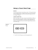
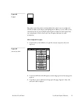
Press ADD to add a button to NEW PAGE. The message bar shown in Figure
43 instructs you how to add a button. The first touch point is the upper-left
corner of the button.

TOUCH AND DRAG FOR SIZE

EXIT

3. 

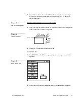
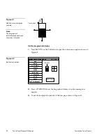
Drag your finger horizontally across the screen and down to set the height and
width of the button as shown in Figure 44.

 Width

Height

Touch point

4. 

Press EXIT in the Editor bar to exit add mode.

Resize the button

1. 

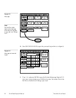
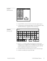
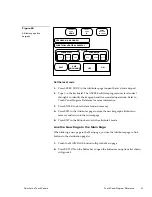
Press BUTTON on the Editor bar again to open the menu options shown in
Figure 45.

PAGE:  NEW PAGE

EXIT

ADD

MOVE

COPY IMAGE

DELETE

RESIZE

EDIT TEXT

ATTRIBUTES

SAVE

PASTE

Button

SET TO DEFAULT

2. 

Press the RESIZE option to resize the button when the message bar appears.

Figure 43

Add a button message bar

Figure 44

Add a button example

Figure 45

Button menu options

Содержание AXT-CV TiltScreen CATP

Страница 1: ...Color Active Touch Panels Firmware version G2 or lower Instruction Manual t a k e c o n t r o l ...

Страница 2: ...by you for a third party This limitation of liability applies whether damages are sought or a claim is made under this warranty or as a tort claim including negligence and strict product liability a contract claim or any other claim This limitation of liability cannot be waived or amended by any person This limitation of liability will be effective even if AMX or an authorized representative of AM...

Страница 3: ...surfaces 7 AXU CV PB or AXU CA PB and BB TP1 plasterboard 9 AXM CV PB or AXM CA PB rack mount 12 Wiring the Touch Panels 13 Guidelines 13 Preparing captive wires 14 Using the AXlink 4 pin connector UniMount and Rack Mount 14 Using the AXlink 4 pin connector and external 12 VDC power supply 15 Using the RS 232 DB9 connector for mouse control or data 15 Cleaning the Touch Overlay 16 Touch Panel Basi...

Страница 4: ...tton 30 Resize the button 31 Button Attributes 32 Set the button attributes 32 Set the border 33 Set the channel code 34 Set the page flip 34 Add Text 34 Add text to a button 34 Create a Joystick 36 Add a joystick on a page 36 Set the joystick attributes 37 Set the level code 38 Create a Bargraph 38 Add a bargraph to a page 39 Set the bargraph attributes 40 Set the level code 41 Link the New Page ...

Страница 5: ...the Protected Setup Page 55 Protected Setup Page Buttons 55 Editor 55 Setup password 56 Auto assign 57 Serial Master Mode 57 Mouse Button 58 Power Up Message 59 Set device 60 Page password 61 Power up page 61 BUS MODE RS 232 MODE BOTH MODE 62 BAUD rate 62 Calibrate 62 Page tracking 63 LCD timer message 63 LCD time out brightness 66 Editor bar 66 Button Menu Options 67 Add 67 Move 68 Copy image 68 ...

Страница 6: ...6 char term 84 32 char term 85 Vertical graph 85 Set color 87 Icon feedback 88 Set color 90 Joystick 91 Set color 93 Drawings 94 Brightness 95 System Menu Options 95 Clear buttons 96 Clear drawings 97 Clear symbols 98 Memory 98 Send file 99 Receive file 100 Move edit bar 100 Print 100 Function map 101 Function show 103 AXCESS Programming 105 Overview 105 System Send_Commands 105 Variable Text Send...

Страница 7: ... CV and AXT CA CATPs 119 AXU CV PB AXU CA PB AXM CV PB and AXM CA PB 120 EXM 1 MB Memory Upgrade 123 Operation 123 AXT CV and AXT CA CATPs 123 AXU CV PB and AXM CV PB 124 Specifications 127 Overview 127 AXT CV and AXT CA 127 AXU CV PB and AXU CA PB Color Active Matrix UniMount Touch Panels 129 AXM CV PB and AXM CA PB Color Active Matrix Touch Panels 130 Technical Support 131 Overview 131 Index 133...

Страница 8: ...vi Table of Contents Color Active Touch Panels ...

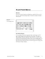
Страница 9: ... use a microprocessor to control a wide range of audiovisual products With the self contained CATP operating system you can create custom pages with buttons icons sliders and bargraphs and import logos and drawings You can also use the TPDOC or TPDesign custom touch panel design programs AMX offers to enhance your CATP designs Figure 1 shows an AXT CV TiltScreen color active video touch panel Figu...

Страница 10: ...0 x 480 HV pixel color active LCD Up to 16 external push buttons 8 on either side of display Microsoft or Logitech mouse compatible Panel programming screens and drawings that can be uploaded and downloaded with TPDOC MS DOS or TPDesign Windows touch panel design programs Internal RS 232 ports for mouse and or RS 232 communication Applications AMX CATPs can control a wide variety of equipment conn...

Страница 11: ...sign touch panel pages and perform touch panel operations What s in this Manual This manual provides basic instructions on how to perform installation and how to use the CATP operating system Installing the Touch Panel Installation wiring and cleaning instructions Touch Panel Basics Basic elements associated with the CATP operating system such as button types message and editor selection bars and ...

Страница 12: ...B Memory Upgrade Step by step instructions to install the optional EXM 1MB Memory Upgrade integrated circuits ICs in the CATP Specifications Touch panel dimensions LCD screen dimensions weight power memory enclosure type and color active accessories and software programs Technical Support Helpful hints you can use to check panel wiring correct a software program problem and the numbers to call for...

Страница 13: ...and Rack Mount CATPs The TiltScreen CATP can be mounted on any flat surface AXU CV PB AXU CA PB and low profile back box Mount the AXU CV PB AXU CA PB and low profile back box Figure 4 Low profile back box AXU CV PB or AXU CA PB bezel Release slot Engraved overlay 1 Make a cutout in the surface according to the dimensions shown in Figure 5 for a low profile back box Figure 4 AXU CV PB or AXU CA PB...

Страница 14: ...sert positions as shown in Figure 4 4 Remove the AXU CV PB or AXU CA PB and drill four 6 32 insert holes Then place a threaded insert into each hole 5 Attach the data and power wiring to the AXU CV PB or AXU CA PB Refer to Wiring the Touch Panels for wiring diagrams and pinout descriptions 6 Fasten the AXU CV PB or AXU CA PB and low profile back box to the surface using the 6 32 machine screws sup...

Страница 15: ...unting flanges Knockout BB TP1 UniMount Back Box enclosure AXU CV PB or AXU CA PB bezel Engraved overlay Stud mounting holes 1 Cut the solid surface according to the cutout dimensions shown in Figure 7 2 Insert a flat head screwdriver into the release slot on the AXU CV PB or AXU CA PB s bezel and remove the engraved overlay Figure 6 AXU CV PB or AXU CA PB and BB TP1 UniMount Back Box enclosure fo...

Страница 16: ...y established This drawing the extent the information has been known shall be confidential except to contained herein that is not generally of AMX CORPORATION All information NOTICE This drawing is the property DWG NO SIZE C DESCRIPTION REV IN CORNERS 125 MAX RADIUS CUTOUT 187 DIA 4 HOLES 11 40 11 85 12 60 FRAME 6 50 6 88 FRAME 55 5 40 2 94 INSTALLATION METH USE WHEN INSTALLING UNIT ON SOLID SURFA...

Страница 17: ...ed 8 Thread the incoming AXlink and RS 232 wiring through the BB TP1 knockout 9 Fasten the BB TP1 to the solid surface with the mounting screws supplied with the enclosure 10 Connect the AXlink and RS 232 wiring to the AXU CV PB or AXU CA PB circuit card Refer to Wiring the Touch Panel for complete wiring information 11 Fasten the AXU CV PB or AXU CA PB to the BB TP1 with the 6 32 screws provided ...

Страница 18: ...IA 4 HOLES TWO 170 DIA HOLES PROVIDED ON ALL SIDES OF BACK BOX FOR STUD MOUNTING STUD MOUNTING OPTION 11 40 35 11 85 125 12 10 12 60 FRAME 2 80 2 80 6 50 6 88 FRAME 55 5 40 2 94 1 Cut the surface according to the cutout dimensions shown in Figure 9 Figure 8 AXU CV PB and BB TP1 for plasterboard ...

Страница 19: ...AXU CV PB s or AXU CA PB s bezel and remove the engraved overlay 3 Lay the AXU CV PB or AXU CA PB facedown onto a soft cloth and remove the four screws from the low profile back box Remove the back box and discard 4 Place the BB TP1 into the cutout and mark the threaded insert positions as shown in Figure 9 5 Remove the BB TP1 and drill four 6 32 insert holes Then place a threaded insert into each...

Страница 20: ...B rack mount Mount the AXM CA PB or AXM CA PB Figure 10 rack mount into an electronic equipment rack 1 Thread the incoming AXlink and RS 232 optional wiring through the opening in the equipment rack 2 Disconnect the AXlink connector from the AMX Control System that supplies power and data to the AXM CV PB or AXM CA PB Then disconnect the DB9 connector from the external RS 232 device connected to t...

Страница 21: ...Video connector video models only Guidelines Touch panels require 12 VDC power to operate properly The AXCESS Control System supplies power via the AXlink cable The maximum wiring distance between the control system and CATP is determined by power consumption supplied voltage and the wire gauge used for the cable Figure 13 lists wire sizes and the maximum lengths allowable between the CATP and con...

Страница 22: ... a soldering iron 2 Insert each wire into the appropriate opening on the connector according to the wiring diagrams and connector types described in this section 3 Turn the flat head screws clockwise to secure the wire in the connector Using the AXlink 4 pin connector UniMount and Rack Mount Connect the control system s AXlink connector to the AXlink connector male on the rear panel of the CATP fo...

Страница 23: ...gure 13 Make sure to connect only the GND wire on the AXlink connector when using a 12 VDC power supply Do not connect the PWR wire to the AXlink connector s PWR terminal on the Control System side of the connector Using the RS 232 DB9 connector for mouse control or data The dual function RS 232 DB9 connector in the touch panels support most standard serial mouse control devices and RS 232 communi...

Страница 24: ... 1 Disconnect the AXlink and RS 232 connector from the CATP 2 Obtain a clean cotton cloth Spray a small amount of cleaning solution consisting of 50 percent isopropyl alcohol and 50 percent water onto the cloth 3 Clean the touch panel overlay with the damp cloth Then wipe the touch panel overlay with a dry cloth 4 Reconnect the AXlink and RS 232 connector to the CATP ...

Страница 25: ...argraphs sliders and drawings to a CATP page and then designate the control functions for each object The number of objects depends on the type and quantity of external devices you want to control with the CATP and AXCESS Control System When you create multiple pages you must link them with buttons Figure 18 shows how to link five CATP pages to the Main page Note that each page contains one button...

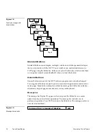
Страница 26: ... General Buttons General buttons are part of the CATP software program and cannot be changed You use general buttons to specify panel communication parameters and create or revise pages Some button examples include the message bar Editor bar selection adjustment keypad page menu decision status and keyboard Message bar The message bar Figure 19 appears when you press the Editor bar or a menu optio...

Страница 27: ...s MAIN PAGE TIME DATE ETIMER 16CHARTERM 32CHARTERM VERTICALGRAPH ICONFEEDBACK JOYSTICK DRAWINGS BRIGHTNESSS BUTTON PAGE ICONS SYSTEM EXIT VIDEOWINDOW VIDEO SETUP Editor bar Selection button Selection buttons Figure 21 appear throughout the color active and color active video touch panel software program to open pages activate YES NO prompt messages or set communication parameters PROTECTED SETUP F...

Страница 28: ...touch panel BAUD 19 2 Button title Variable data Keypad buttons The keypad button opens a keypad Figure 24 so you can enter a password or value assignment All keypad buttons are interactive except for the entry display 0 SET TIME SET 1 2 3 4 5 0 6 0 7 8 9 Entry display Keypad entry 0 9 CLEAR Resets entry to 0 ENTER Processes entry if correct CLEAR ENTER Page menu buttons The page menu button Figur...

Страница 29: ...e Decision buttons Decision buttons Figure 26 appear when an operation has two options YES NO Decision Text Goes Here Decision buttons appear when you exit the Editor bar send or receive a drawing designate a communication protocol or make an operation error Status buttons Status buttons Figure 27 appear when you try to perform operations that do not function correctly NO COMMUNICATION TOUCH SCREE...

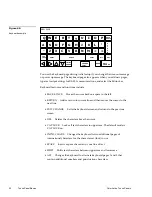
Страница 30: ...ves the cursor back one space to the left RETURN Adds a return to current line and then moves the cursor to the next line EXIT CHANGE Exits the keyboard screen and returns to the previous screen DEL Deletes the character above the cursor CAP LOCK Locks all text characters in uppercase The default mode is CAP LOCK on INTNL CHARS Changes the keyboard to two additional pages of international characte...

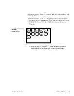
Страница 31: ...e standard fonts four outline fonts and two symbol buttons You can use the FIXED SYMBOLS and VARIABLE SYMBOLS for buttons sliders and bargraphs A a A a Aa A a B b A a B b C c Aa A a A a Aa Aa F I X E D S Y M B O L S V A R I A B L E S Y M B O L S FIXED SYMBOLS Opens the Fixed Symbol pages that contain 22 control symbols Figure 30 shows the first page of fixed symbols Figure 29 Font page example ...

Страница 32: ...iable symbol page example Refer to the TPDOC or TPDesign instruction manuals to download symbols into CATP memory ABORT Closes the keyboard page without making any text or graphic character changes EXIT SAVE Closes the keyboard page and stores the text or graphic changes to memory Figure 30 Fixed Symbol page 1 Figure 31 Variable Symbols page example ...

Страница 33: ...he operations you can use to design CATP pages Activate the Editor bar Before you can design a CATP page you need to activate the Editor bar When you power up the panel the first page you should see is the Main page Figure 32 If you have a pre programmed panel you may not see the Main page Refer to the Editor bar and Go to information in the Touch Panel Program Reference section to access the Main...

Страница 34: ...TIME AND DATE BRIGHTNESS DOUBLE BEEP PROTECTED SETUP SET BACKGROUND BEEP 1 LCD TIMER 15 MIN AXlink vX XXV SERIAL NO 923 00 0001 Wave Pack COMPARE DEVICE SHOW DEVICE Standard Memory AXlink SET TIME AND DOUBLE BEEP 1 2 3 4 5 0 6 1988 7 8 9 CLEAR ENTER 3 Type 1988 and press ENTER to open the Protected Setup page Figure 35 If you enter a wrong number press CLEAR and re enter the number Refer to the Se...

Страница 35: ...MODE PAGE TRACKING BUS MODE POWER UP MESSAGE BAUD 19 2 LCD TIMEOUT BRIGHTNESS 0 4 Press EDITOR Figure 35 and EXIT to close the Protected Setup page and return to the Main page The Editor bar appears at the top of the Main page Figure 36 BUTTON PAGE ICONS SYSTEM EXIT SETUP MAIN PAGE Editor bar Create a Page You create CATP pages using the Page menu option in the Editor bar Figure 35 Protected Setup...

Страница 36: ...ETE GO TO PASSWD PG FLIP PRINT PAGE COLOR 2 Press the ADD option to add a new page and then the add page message to open keyboard page 1 Figure 38 CURRENT PAGE IS MAIN PAGE EXIT ADD COPY RENAME DELETE GO TO PASSWD PG FLIP PRINT PAGE COLOR YOU MUST GIVE THE NEW PAGE A UNIQUE NAME UP TO 20 LETTERS TOUCH SCREEN TO CONTINUE Figure 37 Page menu options Figure 38 Add page message and keyboard page 1 ...

Страница 37: ... O P H J K L N M BACK SPACE SHIFT SPACE ALT INTNL CHARS R E T U R N DEL CHANGE FONT ABORT EXIT CHANGE B 4 Press EXIT CHANGE to add NEW PAGE to panel memory the keyboard closes and returns to the Main page Go to NEW PAGE 1 Press PAGE on the Editor bar to open the page menu options shown in Figure 40 CURRENT PAGE IS MAIN PAGE EXIT ADD COPY RENAME DELETE GO TO PASSWD PG FLIP PRINT PAGE COLOR Figure 3...

Страница 38: ...ess ENTER to go to NEW PAGE Create a Button You should be on NEW PAGE and the Editor bar should be visible before you create a button If not start at the beginning of this section Add a button 1 Press BUTTON on the Editor bar to open the button menu options shown in Figure 42 CURRENT PAGE IS NEW PAGE EXIT ADD MOVE COPY IMAGE DELETE RESIZE EDIT TEXT ATTRIBUTES SAVE PASTE SET TO DEFAULT Figure 41 Pa...

Страница 39: ... to set the height and width of the button as shown in Figure 44 Width Height Touch point 4 Press EXIT in the Editor bar to exit add mode Resize the button 1 Press BUTTON on the Editor bar again to open the menu options shown in Figure 45 PAGE NEW PAGE EXIT ADD MOVE COPY IMAGE DELETE RESIZE EDIT TEXT ATTRIBUTES SAVE PASTE Button SET TO DEFAULT 2 Press the RESIZE option to resize the button when th...

Страница 40: ...bar to exit resize mode Button Attributes You can use the ATTRIBUTES option on the Editor bar to set button borders page flips and assign channel and level codes Set the button attributes 1 Press BUTTON on the Editor bar to open the button menu options shown in Figure 47 CURRENT PAGE IS NEW PAGE EXIT ADD MOVE COPY IMAGE DELETE RESIZE EDIT TEXT ATTRIBUTES SAVE PASTE Button SET TO DEFAULT Figure 46 ...

Страница 41: ...CHANNEL OFF CHANNEL ON BORDER BORDER FILL FILL TEXT TEXT RED RED WHITE WHITE BLUE BLUE Set the border 1 Press BORDER to open the Border options page Figure 49 SINGLE WIDE DOUBLE WIDE NO BORDER SINGLE DIAMOND TRIPLE WIDE SINGLE RAISED DOUBLE RAISED SINGLE ROUNDED DOUBLE ROUNDED TRIPLE RAISED DOUBLE 3 SINGLE SHADOW NO BORDER SPECIAL DOUBLE 2 SINGLE DOUBLE DIAMOND THREE DIMENSION 2 Press SHADOW to re...

Страница 42: ... open the page list Figure 50 NEW PAGE NONE ENTER PREVIOUS MAIN PAGE 2 Press the up or down arrow to move the highlight bar to MAIN PAGE 3 Press ENTER to set the page flip to the MAIN PAGE 4 Press EXIT in the Attributes page to store the new button attributes in memory and return to the current page 5 Press EXIT in the Editor bar to exit the attribute s mode Add Text You can add text to buttons jo...

Страница 43: ...T A S D F G Z X C V CAP LOCK SHIFT Y U I O P H J K L N M BACK SPACE SHIFT SPACE ALT INTNL CHARS R E T U R N DEL CHANGE FONT ABORT EXIT CHANGE B 4 Type MAIN PAGE The text appears in the message box at the top of the keyboard as shown in Figure 52 The CATP displays an error message if you exceed the maximum character spaces in the button Change the size of the button or reduce the text string to cle...

Страница 44: ...y not work properly Refer to Touch Panel Program Reference for more information Add a joystick on a page 1 Press ICONS on the Editor bar to open the icons menu options shown in Figure 54 TIME DATE E TIMER 16 CHAR TERM 32 CHAR TERM VERTICAL GRAPH ICON FEEDBACK JOY STICK DRAWINGS BRIGHTNESS BUTTON PAGE ICONS SYSTEM EXIT VIDEO WINDOW VIDEO SETUP 2 Press the JOYSTICK option to add a joystick when the ...

Страница 45: ... PAGE EXIT ADD MOVE COPY IMAGE DELETE RESIZE EDIT TEXT ATTRIBUTES SAVE PASTE Joystick MAIN PAGE SET TO DEFAULT 2 Press ATTRIBUTES to set the joystick attributes when the message bar appears 3 Touch the joystick to open the Joystick Attributes page shown in Figure 57 Figure 55 Add a joystick example Note The joystick frame will appear when the screen is touched Figure 56 Button menu options ...

Страница 46: ...oard The AXCESS software program uses level codes 1 through 7 to identify the joystick and its associated operations Refer to Touch Panel Program Reference for more information 3 Press ENTER to store the level code in memory 4 Press EXIT in the Attributes page to store the new joystick attributes in memory and return to the current page 5 Press EXIT in the Editor bar to exit the attribute s mode C...

Страница 47: ...anel Program Reference for more information Add a bargraph to a page 1 Press ICONS on the Editor bar to open the icons menu options shown in Figure 60 TIME DATE E TIMER 16 CHAR TERM 32 CHAR TERM VERTICAL GRAPH ICON FEEDBACK JOYSTICK DRAWINGS BRIGHTNESS BUTTON PAGE ICONS SYSTEM EXIT VIDEO WINDOW VIDEO SETUP 2 Press the VERTICAL GRAPH option to add a bargraph when the message bar appears 3 Touch the...

Страница 48: ...W PAGE EXIT ADD MOVE COPY IMAGE DELETE RESIZE EDIT TEXT ATTRIBUTES SAVE PASTE Bar graph MAIN PAGE SET TO DEFAULT 2 Press ATTRIBUTES to set the bargraph attributes when the message bar appears 3 Touch the bargraph to open the Attributes page shown in Figure 63 Figure 61 Add and move a bargraph example Note The bargraph will automatically appear when the screen is touched Figure 62 Button menu optio...

Страница 49: ...ph and its associated operations Refer to Touch Panel Program Reference for more information 3 Press ENTER to store the level code in memory 4 Press EXIT in the Attributes page to store the new bargraph attributes in memory and return to the current page 5 Press EXIT in the Editor bar to exit the attribute s mode Link the New Page to the Main Page When linking a new page to the Main page you use t...

Страница 50: ...page Press DEL four times to delete MAIN 5 Type NEW The revised text appears in the keyboard window as shown in Figure 65 NEW Q W E R T A S D F G Z X C V CAP LOCK SHIFT Y U I O P H J K L N M BACK SPACE SHIFT SPACE ALT INTNL CHARS R E T U R N DEL CHANGE FONT ABORT EXIT CHANGE B 6 Press EXIT SAVE to close the keyboard 7 Press EXIT in the Editor bar to exit edit text mode 8 Press BUTTON on the Editor...

Страница 51: ...HANGE OFF ON SET COLOR CHANNEL OFF CHANNEL ON RED RED WHITE WHITE BLUE BLUE BORDER FILL TEXT FILL BORDER TEXT 10 Press PAGE in the Attributes page to open the page list 11 Press the up or down arrow to move the highlight bar to NEW PAGE 12 Press ENTER to set the page flip to the NEW PAGE 13 Press EXIT in the Attributes page to store the new button attributes in memory and return to the current pag...

Страница 52: ... After you finish designing the CATP page close the Editor bar by pressing EXIT on the Editor bar Exit editor mode 1 Touch EXIT on the Editor bar Figure 68 BUTTON PAGE ICONS SYSTEM EXIT SETUP NEW PAGE 2 Press YES on the exit decision box to close the Editor bar Figure 68 Main page ...

Страница 53: ... page and Editor bar operations to create CATP pages This section describes operations access flowcharts and button options Setup Page You can access the Setup page from the Main page Figure 69 which appears when you power up the CATP SETUP MAIN PAGE The buttons in the Setup page set the operating parameters of the CATP Figure 69 Main page ...

Страница 54: ...Pack or When you select the SETUP button it changes to a dark background The flowchart in Figure 71 shows the buttons you use to access the Setup page MAIN PAGE SETUP BUTTON Buttons Use the Setup page buttons to configure the CATP Beep The BEEP button Figure 72 sets how long the audible beep sounds when you press the screen Figure 70 Setup page Note The SmartPack button appears in the Setup page w...

Страница 55: ...rrows to change the time that the timer screen stays on when there is no panel activity The minimum time setting is 1 and maximum is 150 Serial number AXlink and vX XX The AXlink SERIAL NO and vX XX buttons shown in Figure 74 are non buttons display only AXlink vX XXV SERIAL NO 940 XX XXXX A capital V at the end of the version number indicates that it is a video touch panel The AXlink button is an...

Страница 56: ...E MODULE VERSION BATTERY VOLTAGE 12 5v BATTERY SUPPLY VOLTAGE 12 5v SLEEP TIME OFF RF OFF IR OFF The SmartPack page shows the module type module version battery voltage level power supply voltage level battery charge status and sets the sleep time RF signal and IR signal SMT PK MODULE Appears when an optional SMT PK is connected to the CATP MODULE VERSION vX XX Shows the ROM firmware version insta...

Страница 57: ...ol signals on or off IR 38 kHz IR 455 kHz IR OFF Press to set IR control signals to 38 kHz 455 kHz or off WAV PK The WAV PK button appears on the Setup page when a WAV PK WavePack is connected to a TiltScreen CATP The WAV PK provides wireless two way RF spread spectrum touch panel control The WAV PK contains a lead acid rechargeable battery that supplies independent power to the CATP Refer to the ...

Страница 58: ...itch setting on the WAV PK Refer to the AXR WAVES Server and Wireless Power Packs instruction manual to set the group ID number RSSI Shows the strength of the AXR WAVES Server signal received by the CATP The shaded area in the horizontal gauge moves from left to right as the RF signal intensity increases The shaded area should fluctuate between 50 and 100 BATTERY CHARGING BATTERY FULLY CHARGED The...

Страница 59: ...on about device and group ID settings NETWORK EFFICIENCY XX Shows the communication status of bi directional RF transmissions between all the CATPs and AXR WAVES Server The percentage of efficiency 0 100 is calculated by the number of retries required to perform a panel operation SERVER DEVICES Shows the AXlink device number of the TiltScreen CATPs communicating with the AXR WAVES Server Set time ...

Страница 60: ...Press the DOUBLE BEEP button Figure 78 to enable or disable the double beep option The double beep sounds when you press the screen When the button background and text is black the double beep is enabled and when the background is white and text is black it is disabled DOUBLE BEEP Disabled DOUBLE BEEP Enabled Set the BEEP button described earlier to 0 to disable the beep sound Protected setup The ...

Страница 61: ...ction Set background Press the SET BACKGROUND button to open the page shown in Figure 80 ADJUST ATTRIBUTES TO DESIRED LEVELS EXIT SET TIME AND DATE BRIGHTNESS DOUBLE BEEP PROTECTED SETUP SET BACKGROUND BEEP 1 LCD TIMER 15 MIN AXlink vX XXV SERIAL NO 940 XX XXXX Wave Pack COMPARE DEVICE SHOW DEVICE STANDARD MEMORY BLACK DARK DARK DARK DARK RED GREEN YELLOW BLUE DARK DARK LIGHT MONEY SKY MAGENTA CYA...

Страница 62: ...rrows to set the screen brightness The minimum brightness level is 1 and the maximum is 8 Protected Setup Page The Protected Setup Page allows you to set passwords mouse controls and communications parameters The flowchart in Figure 82 shows how to access the Protected Setup Page SETUP BUTTON MAIN PAGE PROTECTED SETUP BUTTON TYPE 1988 The Protected Setup Page is password protected so when you pres...

Страница 63: ...RED LEVEL EXIT SYMBOL EDITOR EDITOR CALIBRATE SETUP PASSWORD PAGE PASSWORD AUTO ASSIGN POWER UP PAGE LCD TIMER MESSAGE MOUSE SET DEVICE 128 POWER UP MESSAGE BUS MODE SERIAL MASTER MODE PAGE TRACKING BAUD 19 2 LCDTIMEOUT BRIGHTNESS 0 Protected Setup Page Buttons Use the Protected Setup page buttons to set the edit option and system parameters Editor Press the EDITOR button to activate the Editor ba...

Страница 64: ...e there are so many operations associated with the Editor bar they are described in the Editor bar subsection BUTTON PAGE ICONS SYSTEM EXIT SETUP MAIN PAGE Editor bar Setup password Press the SETUP PASSWORD button to open the password keypad Figure 86 and change the Setup page password number AXlink v2 xx SET TIME AND DATE SET DOUBLE BEEP 0 SET TIME SET 1 2 3 4 5 0 6 1988 7 8 9 CLEAR ENTER Figure ...

Страница 65: ...annel code numbers are used by the CATP and AXCESS Control System to keep track of operations you assign to each button Auto Assign is on when the button background is black with white text and off when the button background is white with black text Figure 87 AUTO ASSIGN AUTO ASSIGN On Off Serial Master Mode Press the SERIAL MASTER MODE button to change the Program Port from the MASTER to the touc...

Страница 66: ...PORT FROM THE MASTER TO THE TP Mouse Button In protected Setup mode press MOUSE and the page show in Figure 89 appears for setting the following mouse parameters EXIT SET MOUSE ATTRIBUTES MOUSE OFF SPEE 8 MICROSOFT MOUSE BORDER COLOR FILL COLOR Border color Fill color SPEED Increases or decreases the movement speed of the mouse pointer with the up and down arrows Minimum slow speed is 1 and the ma...

Страница 67: ...or of the mouse pointer arrow Power Up Message Pressing the POWER UP MESSAGE Figure 90 button produces the keyboard page Type the message you want displayed when the touch panel first becomes active Q W E R T A S D F G Z X C V CAP LOCK SHIFT Y U I O P H J K L N M BACK SPACE SHIFT SPACE ALT INTNL CHARS R E T U R N DEL CHANGE FONT ABORT EXIT CHANGE B BACK SPACE Moves the cursor back one space to the...

Страница 68: ... text FONT Not functional for this operation ABORT Closes the keyboard page without making any text or graphic character changes EXIT SAVE Closes the keyboard page and stores the text to memory Set device Press the SET DEVICE button to open the device number keypad Figure 91 and enter an AXlink device number the range is 1 through 255 1 2 3 4 5 0 6 128 7 8 9 CLEAR ENTER The device number identifie...

Страница 69: ...Clears the keypad number ENTER Sets the page password number closes the keypad and returns to the Protected Setup page Power up page Press the POWER UP PAGE button to open the Power up page list Figure 92 NONE ENTER PREVIOUS MAIN PAGE Select a page to designate the first page to open when you power up the CATP Move the highlight bar to a page name NONE or PREVIOUS using the up and down arrows Pres...

Страница 70: ...he data communication speed for the CATP s RS 232 port DB9 connector The baud rates are 300 600 1 200 2 400 4 800 9 600 19 200 and 38 400 Calibrate Press the CALIBRATE button to open the decision box Figure 93 and reset the vertical and horizontal touch points on the screen YES NO THIS FUNCTION IS FACTORY SET PRESS NO TO EXIT YES Starts the calibration test Carefully press each crosshair using you...

Страница 71: ... used to control pages in another CATP Page tracking is on when the button background is black with white text Figure 94 and off when the background is white with black text PAGE TRACKING PAGE TRACKING On Off LCD timer message Press the LCD TIMER MESSAGE button to open the page shown in Figure 95 TEXT MESSAGE CLOCK DISPLAY DRAWING VIDEO The LCD Timer Message appears when the CATP is in screen save...

Страница 72: ...ault mode is CAP LOCK on INTNL CHARS Changes the keyboard to two additional pages of international characters for the character set font in use SPACE Inserts a character space in your line of text SHIFT Shifts text characters between uppercase and lowercase ALT Changes the keyboard to alternate keyboard pages that contain additional numbers and punctuation characters Direction arrows Moves the cur...

Страница 73: ...gure 99 Select a drawing to appear when the CATP is in screen saver mode Refer to System Menu Options subsection for more information about drawings NONE ENTER Direction arrows Moves the cursor left right up and down within a line or page of text Up arrow Moves the highlight bar up Down arrow Moves the highlight bar down ENTER Sets the drawing to appear in screen saver mode and returns to the Prot...

Страница 74: ...rs on every page The flowchart in Figure 100 shows the sequence to activate the Editor bar SETUP MAIN PAGE PROTECTED SETUP EXIT BUTTON EDITOR BUTTON TYPE 1988 When you press the EXIT button in the Protected Setup page Figure 101 you return to the Main page Figure 102 and the Editor bar appears at the top of the page ADJUST ATTRIBUTES EXIT SYMBOL EDITOR EDITOR CALIBRATE SETUP PASSWORD PAGE PASSWORD...

Страница 75: ... in Figure 103 PAGE NEW PAGE EXIT ADD MOVE COPY IMAGE DELETE RESIZE EDIT TEXT ATTRIBUTES SAVE PASTE The options include operations to create configure and revise buttons The Editor bar shown at the top default of the screen shows the page name Press EXIT to close the option s list Add Press the ADD option and add a button when the message bar appears The first touch point is the upper left corner ...

Страница 76: ...he new position The X and Y coordinates show the button position on the screen Press the EXIT button in the Editor bar to exit X 92 Y 140 DRAG BUTTON EXIT Copy image Press the COPY IMAGE option to copy a button joystick or bargraph when the message bar Figure 106 appears on the screen X 92 Y 140 DRAG TO COPY EXIT Press the target button joystick or bargraph and drag the button copy to the new posi...

Страница 77: ... bargraph and returns to the current page Press the EXIT button in the Editor bar to exit NO Cancels the deletion process and returns to the current page Press the EXIT button in the Editor bar to exit Resize Press the RESIZE option to resize a button when the message bar Figure 109 appears TOUCH AND DRAG TO RESIZE EXIT Drag your finger horizontally across the screen and down to resize the width a...

Страница 78: ...d pages 1 and 2 You can alternate between the keyboard pages using the MORE KEYS button The text appears in the message box at the top of the keyboard page The CATP opens an error message if the text string exceeds the space in the button Change the size of the button or reduce the font size to clear the error message Special keyboard button descriptions include BACK SPACE Moves the cursor back on...

Страница 79: ...s and punctuation characters Direction arrows Moves the cursor left right up and down within a line or page of text FONT Opens the Font page Figure 112 Select a font typeface for the button text Aa Aa Aa AaBb AaBbCc Aa Aa Aa Aa Aa FIXED SYMBOLS VARI ABLE SYMBOLS Fixed Symbols Opens the Fixed Symbols keyboard page that contains factory default symbols shown in Figure 113 The CATP opens an error mes...

Страница 80: ...TP memory Figure 114 shows an example of custom symbols The CATP opens an error message if you exceed the space in the button ABORT Closes the keyboard pages without making any text or graphic character changes EXIT SAVE Closes the keyboard pages and stores the text to memory Figure 113 Fixed Symbols keyboard page Figure 114 Variable Symbols keyboard page ...

Страница 81: ...EL OFF CHANNEL ON BORDER BORDER FILL FILL TEXT TEXT RED RED WHITE WHITE BLUE BLUE BORDER Opens the Border Options page Figure 116 so you can select a border style SINGLE WIDE DOUBLE WIDE NO BORDER SINGLE DIAMOND TRIPLE WIDE SINGLE RAISED DOUBLE RAISED SINGLE ROUNDED DOUBLE ROUNDED TRIPLE RAISED DOUBLE 3 SINGLE SHADOW NO BORDER SPECIAL DOUBLE 2 SINGLE DOUBLE DIAMOND THREE DIMENSION Determine the bo...

Страница 82: ...BRING BUTTON TO FRONT Changes the alignment position of two buttons This option stacks buttons for complex page arrangements PAGE Opens the page list Figure 117 so you can select a page flip PAGE 4 NONE ENTER PREVIOUS MAIN PAGE PAGE 3 PAGE 2 PAGE 1 Move the highlight bar to a page name NONE or PREVIOUS using the up and down arrows Press ENTER to set the page Press PREVIOUS to set the button to ret...

Страница 83: ...rogramming Guide for more information KEYBOARD Sets the STRING attribute to SPECIAL KEYBOARD The special keyboard option sends messages to the control system to perform an operation defined in the AXCESS software program When you press the button a keyboard appears and you enter a message and press EXIT CHANGE The CATP sends the message to the AXCESS Control System to perform an operation Refer to...

Страница 84: ...order fill and text to match the CHANNEL ON options in the Attributes page when the assigned button function is on MOMENTARY Sets the button border fill and text to match the CHANNEL ON options in the Attributes page when you press the button regardless of the assigned function EXIT Closes the Attributes page and returns to the current page EXIT NO CHANGE Cancels changes closes the Attributes page...

Страница 85: ...sword page flip and print CATP pages Press the EXIT button on the Editor bar to close the menu options Add Press the ADD option to add a new CATP page and then the add page message to open the keyboard Figure 121 Touch the screen and the keyboard page will then appear CURRENT PAGE IS MAIN PAGE EXIT SETUP MAIN PAGE ADD COPY RENAME DELETE GO TO PASSWD PGFLIP PRINT PAGE COLOR YOU MUST GIVE THE NEW PA...

Страница 86: ...returns to the current page Copy Press the COPY option to copy the current page and then select the copy page message to open the keyboard Figure 122 CURRENT PAGE IS MAIN PAGE EXIT SETUP MAIN PAGE ADD COPY RENAME DELETE GO TO PASSWD PG FLIP PRINT PAGE COLOR YOU MUST GIVE THE NEW PAGE A UNIQUE NAME UP TO 20 LETTERS TOUCH SCREEN TO CONTINUE Type the new page name using the keyboard pages Choose EXIT...

Страница 87: ...CK SHIFT Y U I O P H J K L N M BACK SPACE SHIFT SPACE ALT INTNL CHARS R E T U R N DEL CHANGE FONT ABORT EXIT CHANGE B Choose EXIT SAVE to store the page name in memory Special keyboard keys are INTNL CHARS ALT ABORT and EXIT SAVE INTNL CHARS Changes the keyboard to two additional pages of international characters for the current character set in use ALT Changes the keyboard to alternate keyboard p...

Страница 88: ...Main page NO Cancels the deletion process and returns to the current page Go to Press the GO TO option to open the page list shown in Figure 125 MAIN PAGE NONE ENTER PREVIOUS PAGE 1 PAGE 2 With the up and down arrows move the highlight bar to a page name NONE or PREVIOUS and press ENTER to go to that page Up arrow Moves the highlight bar up Down arrow Moves the highlight bar down ENTER Resets the ...

Страница 89: ...TO FRONT EXIT EXIT NO CHANGE OFF ON SET COLOR CHANNEL OFF CHANNEL ON BORDER BORDER FILL FILL TEXT TEXT RED RED WHITE WHITE BLUE BLUE Press PAGE to open the page list Figure 127 MAIN PAGE NONE ENTER PREVIOUS PAGE 1 PAGE 2 Move the highlight bar to the target page using the up and down arrows Press ENTER and then EXIT twice to set the new button and page flip Up arrow Moves the highlight bar up Down...

Страница 90: ...OC before you send the print file Refer to TPDOC instruction manuals for more information YES Receives the PC file over the AXlink connector on the CATP and opens the decision box in Figure 128 NO Receives the PC file over the RS 232 connector on the CATP and opens the decision box in Figure 128 YES NO PRESS YES FOR BUS TRANSFER PRESS NO FOR RS232 9 PIN D YES Sends the print file to the PC bus The...

Страница 91: ...y displayed within the vertical graph Channel On Border Select the border color for the vertical graph Fill Select the background fill color for the vertical graph Text Select the color of the text if any displayed within the vertical graph Icons Menu Options Press ICONS to open the menu options shown in Figure 130 TIME DATE E TIMER 16 CHAR TERM 32 CHAR TERM VERTICAL GRAPH ICON FEEDBACK JOY STICK ...

Страница 92: ...apsed timer button Figure 131 to the current page E TIMER 9 59 59 RESET START You can use the elapsed timer to time an event for up to 10 hours Use the ATTRIBUTE option in the Button menu to move the timer on the screen RESET Resets the elapsed timer to 0 00 00 START Starts the elapsed timer and changes the button name to PAUSE PAUSE Pauses the elapsed timer and changes the button name to START Pr...

Страница 93: ...re 132 LEVEL CODE 1 FEEDBACK BAR GRAPH FUNCTION VERTICAL DISPLAY CHANNEL CODE NONE BRING BUTTON TO FRONT EXIT EXIT NO CHANGE OFF ON SET COLOR CHANNEL OFF CHANNEL ON BORDER BORDER FILL FILL TEXT RED RED WHITE WHITE BLUE BLUE CHANNEL CODE Opens the keypad to set the channel code for the vertical graph The channel code range is 1 through 255 Keep track of channel code settings to create duplicate ver...

Страница 94: ...n be set to control a device or display a status change when the CATP is connected to an AXCESS Control System FUNCTION Opens the display options shown in Figure 134 Choose one of the options to set the vertical graph attribute VERTICAL DISPLAY VERTICAL ACTIVE VERTICAL CENTER HORIZONTAL DISPLAY HORIZONTAL ACTIVE HORIZONTAL CENTER VERTICAL DISPLAY Sets the vertical graph as a vertical indicator for...

Страница 95: ... software program When a control level is set on the horizontal graph control data is sent to the control system to control an external device HORIZONTAL CENTER Sets the horizontal graph as a horizontal controller with a default control level Control levels are defined in the AXCESS software program When a control level change is sent to the control system the external device changes accordingly u...

Страница 96: ...eedback can be sent by the CATP or the AXCESS Control System Use the RESIZE option in the Button menu to resize the icon feedback button Use the ATTRIBUTES option in the Button menu to set the icon feedback attributes in the Attributes page Figure 135 STRING NONE FEEDBACK ICON CHANNEL CHANNEL CODE NONE BORDER BRING BUTTON TO FRONT OFF ICON ON ICON EXIT EXIT NO CHANGE OFF ON SET COLOR CHANNEL OFF C...

Страница 97: ...hic illustrations CHANNEL CODE Opens the keypad to set the channel code for the button The channel code range is 1 through 255 Keep track of channel code settings to create duplicate buttons with identical functions on another page BRING BUTTON TO FRONT Sets the alignment position of two or more buttons This option stacks buttons on the page OFF ICON Opens the Variable Symbols keyboard page Figure...

Страница 98: ...an receive feedback control signals from an AXCESS Control System You can use the feedback option to designate how a button appears on the CATP Feedback options are ICON CHANNEL and ICON MOMENTARY ICON CHANNEL ICON MOMENTARY ICON CHANNEL Sets the button s feedback received from the AXCESS Control System ICON MOMENTARY Sets the button s feedback to ON ICON when you press the button and OFF ICON whe...

Страница 99: ...in the icon EXIT Saves the attribute changes closes the Attributes page and returns to the current page EXIT NO CHANGE Cancels the attribute changes closes the Attributes page and returns to the current page Joystick Press the JOYSTICK option and the screen to add a joystick or crosshair icon Figure 139 to the current page Joystick Crosshair You can set the attributes for a joystick or crosshair i...

Страница 100: ...ick or crosshair icon in the AXCESS software program The CATP uses the level code to set the X horizontal position and then adds 1 to that level code to set the Y vertical position For example if you assign level code 7 to a joystick the CATP automatically assigns level code 7 as the X horizontal position and level code 8 as the Y vertical position Refer to the AXCESS Programming Guide for more in...

Страница 101: ...Sets the icon to a four quadrant joystick button with a control stick When you move the control stick the CATP sends feedback data to the control system and to the external device to perform a pre programmed operation When you remove your finger from the screen the control stick and external device stay in that position NON CENTER CROSSHAIR Sets the icon to a four quadrant crosshair button with a ...

Страница 102: ... can add drawings layouts and special shapes to a page The drawings can include hidden buttons that activate areas in the drawing Drawings created externally with computer aided design CAD packages can be saved as CATP files You can also move and resize a button that contains a drawing You can use the TPDOC MS DOS or TPDesign Windows programs to import and resize a wide variety of graphic files an...

Страница 103: ... page from the Protected Setup page ADJUST ATTRIBUTES TO DESIRED LEVELS EXIT BRIGHT 8 BLACK DARK DARK DARK DARK RED GREEN YELLOW BLUE DARK DARK LIGHT MONEY SKY MAGENTA CYAN GRAY GREEN BLUE CREAM MEDIUM DARK RED GREEN YELLOW BLUE MAGENTA CYAN WHITE Set the brightness level for the screen BRIGHT Press the up and down buttons to set the screen brightness The minimum brightness level is 1 and the maxi...

Страница 104: ...t decision box shown in Figure 145 YES NO PRESSING YES WILL DESTROY ALL SYSTEM DATA IN THE PANEL This option erases CATP memory Do not use the clear buttons option unless you truly want to delete all buttons and CATP pages Use the DELETE option in the Button menu to delete one button or DELETE option in the PAGE menu to delete a page YES Confirms the deletion process and opens the decision box sho...

Страница 105: ... option erases deletes the drawing you select in the drawing list YES NO DO YOU WANT TO DELETE ONE OF THE DRAWINGS YES Opens the drawing list shown in Figure 148 NO Opens the decision box in Figure 149 ENTER NONE WELCOME TO AMX DRAWING 2 Up arrow Moves the highlight bar up Down arrow Moves the highlight bar down ENTER Erases deletes drawing and returns to the current page Figure 146 Clear Buttons ...

Страница 106: ...150 YES NO DO YOU WANT TO DELETE ALL OF THE SYMBOLS Memory Press the MEMORY option to open the message box in Figure 151 to show the number of memory blocks available to create pages and buttons THE NUMBER OF AVAILABLE MEMORY BLOCKS 4970 TOUCH SCREEN TO CONTINUE Press the screen again to open the memory blocks used message box shown in Figure 152 This message shows the number of used memory blocks...

Страница 107: ...ESS YES FOR BUS TRANSFER PRESS NO FOR RS232 YES Sends the file to the PC over the AXlink connector on the CATP and opens the decision box in Figure 155 NO Sends the file to the PC over the RS 232 connector on the CATP and opens the decision box in Figure 155 YES NO PRESS YES TO START THE UPLOAD AND NO TO QUIT YES Sends the CATP files to the PC During the upload process you can press the EXIT butto...

Страница 108: ...ector in the CATP and opens the decision box in Figure 157 YES NO THIS WILL DESTROY SOME PANEL DATA PRESS YES TO CONTINUE YES Receives the PC file During the download process you can press the EXIT button when the FILE TRANSFER page appears to cancel the file transfer and return to the current page NO Cancels the file transfer and returns to the current page Move edit bar Press the MOVE EDIT BAR o...

Страница 109: ...mation YES Receives the PC file via the AXlink connector on the CATP and opens the decision box in Figure 159 NO Receives the PC file via the RS 232 connector in the CATP and opens the decision box in Figure 159 YES NO PRESS YES TO START PRESS NO TO QUIT YES Sends the print file to the PC The CATP returns to the startup page when the file transfer is complete NO Cancels the file transfer and retur...

Страница 110: ... 120 211 212 213 214 215 216 217 218 226 227 228 229 230 231 232 233 241 242 243 244 245 245 247 248 129 130 131 132 133 134 135 159 160 161 162 163 164 165 174 175 176 177 178 179 180 189 190 191 192 193 194 195 204 205 206 207 208 209 210 219 220 221 222 223 224 225 234 235 236 237 238 239 240 249 250 251 252 253 354 255 The map contains a 255 button matrix of channel code numbers that are assig...

Страница 111: ...31 232 233 241 242 243 244 245 245 247 248 129 130 131 132 133 134 135 159 160 161 162 163 164 165 174 175 176 177 178 179 180 189 190 191 192 193 194 195 204 205 206 207 208 209 210 219 220 221 222 223 224 225 234 235 236 237 238 239 240 249 250 251 252 253 354 255 The map contains a 255 button matrix of variable text code numbers that are assigned to CATP buttons Variable text code numbers that ...

Страница 112: ...umber appears in the lower right corner of sliders bargraphs and joysticks If a zero appears in a button it does not have a channel code or variable text code assignment Press the FUNCTION SHOW option again to deactivate the channel code and variable text code numbers Figure 162 Function show button and slider example ...

Страница 113: ...tem Send_Commands Command Description ABEEP Output 1 panel beep even if the Beep value is set to 0 in the Setup page Example SEND_COMMAND TP ABEEP Beeps the panel ADBEEP Output a double beep even if the Double Beep value is set to 0 in the Setup page Example SEND_COMMAND TP ADBEEP Double beeps the panel AKEYB text string Open the CATP keyboard and initialize the text string entry The keyboard stri...

Страница 114: ...COMMAND TP AKEYR Closes the keyboard or keypad opened using the AKEYB AKEYP or PKEYP commands BEEP Output 1 beep The Beep button in the Protected Setup page must be set to 1 10 for this command Output 1 beep Example SEND_COMMAND TP BEEP Beeps the panel if the beep is not set to 0 CLOCK mm dd yy hh mm ss Set the time and date mm 01 12 dd 01 31 yy 00 99 hh 00 23 mm 00 59 ss 00 59 Example SEND_COMMAN...

Страница 115: ...splay The keyboard string is set to null during power up and is stored until power down Use the AKEYB command to automatically open a keyboard and display the text string text string 0 59 characters Example SEND_COMMAND TP KEYB TOUCH HERE Initializes the text string entry TOUCH HERE when the CATP keyboard opens KEYP number string Initialize the number string entry when the CATP keypad opens This c...

Страница 116: ...same as power up Data stored in memory is not cleared Example SEND_COMMAND TP RESET Resets the CATP SETUP Go to the Setup page Example SEND_COMMAND TP SETUP Flips the CATP to the Setup page SLEEP Switch the CATP to screen saver mode Example SEND_COMMAND TP SLEEP Activates the screen saver mode ST sleep time Set the time to activate sleep mode for a CATP equipped with a WAV PK wireless power pack W...

Страница 117: ...D TP TPAGEOFF Deactivates the page tracking option TPAGEON Activate page tracking Example program DEFINE DEVICE TP1 128 TP2 129 DEFINE_VARIABLE TP1_BUF 25 TP2_BUF 25 DEFINE_START CREATE_BUFFER TP1 TP1_BUF CREATE_BUFFER TP2 TP2_BUF SEND_COMMAND TP1 TPAGEON SEND_COMMAND TP2 TPAGEON DEFINE_PROGRAM IF LENGTH_STRING TP1_BUF IF FIND_STRING TP1_BUF PAGE 1 ...

Страница 118: ...ne panel and sent to another panel WAKE Deactivate screen saver mode and reset sleep timer Example SEND_COMMAND TP WAKE Deactivates the CATP screen saver mode and resets the sleep timer ZAP Clear all memory and erase buttons pages and drawings Example SEND_COMMAND TP ZAP Clears all memory and erases all buttons pages drawings and symbols Variable Text Send_Commands Use variable text Send_Commands ...

Страница 119: ...extra large 4 large 20 fixed symbols 5 extra large 21 user defined symbols 6 hollow medium 30 logo drawings Example SEND_COMMAND TP FONT1 6 Changes variable text button 1 font to hollow medium F variable text address font size Shorthand version of FONT command variable text address 1 255 font size 1 9 20 21 and 30 Example SEND_COMMAND TP F 1 6 Changes variable text button 1 font to hollow medium F...

Страница 120: ...ouble wide 10 triple wide 3 single raised 11 double single single single 4 double raised 12 triple raised 5 single rounded 13 shadow 6 double rounded 14 no border and no background 7 double single single 15 3 Dimensional Example SEND_COMMAND TP ICON25 6 Changes the variable text button 25 border style to double rounded I variable text address border style Shorthand version of ICON command variable...

Страница 121: ...variable text address 1 255 new button text 1 60 characters Shorthand version of TEXT command Example SEND_COMMAND TP T 1 VCR PLAY Changes the variable text button 1 title to VCR PLAY C variable text address border style font size new button text variable text address 1 255 border style 0 14 font size 1 9 20 21 and 30 Set the border font and text in one command Example SEND_COMMAND TP C 1 6 6 VCR ...

Страница 122: ...D number 0 15 Example ID15 Assigns group ID 15 to the wireless CATP ST sleep time Assign the sleep time to a button with a standard string Set the time to activate sleep mode for a CATP equipped with a WAV PK wireless power pack When the CATP s intime matches the sleep time the panel goes to sleep wireless communication stops and battery discharge is minimized sleep time 0 off 150 minutes Example ...

Страница 123: ...anel This will avoid any inadvertent loss of data or a service outage To replace the lithium batteries you will need a Phillips screwdriver and a non conducting flat blade tool to slip under each battery to pry it out of the socket AXT CV and AXT CA Remove the lithium batteries from the AXT CV and AXT CA 1 Discharge the static electricity from your body by touching a grounded object 2 Remove the A...

Страница 124: ...ard backwards until you can lay it down flat with the batteries exposed 9 Carefully slide the other battery out of its socket and insert the new battery 10 Rotate the circuit card back to the original position and place it in the CATP housing 11 Place the bottom panel on the CATP and align the mounting plate and screw holes Insert the four Phillips head screws and tighten 12 Plug the AXlink connec...

Страница 125: ... header and remove the CATP from the back box or equipment rack 5 Flip the CATP facedown onto a soft cloth and remove the touch overlay s ribbon cable connector and backlight connector from the circuit card Do not remove the cable on the battery side of the circuit card Figure 168 shows the connectors on the circuit card E V E N O D D 8 1 1 5 J1 C O R P 1996 50 0941 REV A AXU CV 5 1 JP1 JP2 JP3 JP...

Страница 126: ...Xlink and RS 232 connector 12 Repeat steps 5 through 10 for the second battery Then go to step 13 13 Return the CATP to the back box or equipment rack and connect the AXlink and RS 232 connector 14 Insert the four mounting screws and tighten 15 Place the engraved overlay onto the AXU CV PB or AXM MLC PB bezel Caution There is a danger of explosion if you replace the batteries incorrectly Replace t...

Страница 127: ...rade into the AXT CV and AXT CA CATP 1 Discharge the static electricity from your body by touching a grounded object 2 Remove the AXlink connector and other connectors if applicable from the rear side of the CATP 3 Flip the CATP face down onto a soft cloth and remove the four Phillips head screws from the bottom panel Then gently remove the panel 4 Gently rotate the circuit card backward until you...

Страница 128: ... the touch panel AXU CV PB AXU CA PB AXM CV PB and AXM CA PB Install the firmware upgrade into the AXU CV PB AXU CA PB AXM CV PB and AXM CA PB touch panels 1 Discharge the static electricity from your body by touching a grounded object 2 Insert a flat blade tool into the release slot on the CATP s bezel and remove the engraved overlay 3 Remove the four 6 32 mounting screws and carefully lean the C...

Страница 129: ...are ICs out of the socket connectors labeled U5 and U6 with a non conducting flat blade tool and insert the two upgrade firmware ICs into sockets U5 and U6 7 Return the touch panel to the back box or equipment rack and connect the AXlink and RS 232 connector 8 Place the touch panel back into the back box or equipment rack and insert the four mounting screws and tighten 9 Place the engraved overlay...

Страница 130: ...122 Firmware Upgrades Color Active Touch Panels ...

Страница 131: ...ory Upgrade into the AXT CV and AXT CA CATP 1 Discharge the static electricity from your body by touching a grounded object 2 Remove the AXlink connector and other connectors if applicable from the rear side of the CATP 3 Flip the CATP face down onto a soft cloth and remove the four Phillips head screws from the bottom panel Then gently remove the panel 4 Gently rotate the circuit card backward un...

Страница 132: ...ectors back into the touch panel AXU CV PB and AXM CV PB Install the EXM 1MB Memory Upgrade into the AXU CV PB or AXM CV PB touch panel 1 Discharge the static electricity from your body by touching a grounded object 2 Insert a flat blade tool into the release slot on the CATP s bezel and remove the engraved overlay 3 Remove the four 6 32 mounting screws and carefully lean the CATP backward to expo...

Страница 133: ... pry the 256KB IC out of the socket connector labeled U4 with a non conducting flat blade tool and insert the two 512K ICs into sockets U3 and U4 7 Return the touch panel to the back box or equipment rack and connect the AXlink and RS 232 4 pin header 8 Place the touch panel back into the back box or equipment rack and insert the four mounting screws and tighten 9 Place the engraved overlay onto t...

Страница 134: ...126 EXM 1 MB Memory Upgrade Color Active Touch Panels ...

Страница 135: ... Overview This section describes the specifications for all color active touch matrix panels AXT CV and AXT CA Figure 173 is a drawing of the AXT CV and AXT CA TiltScreen CATP and Figure 174 lists the specifications Figure 173 AXT CV and AXT CA TiltScreen CATP ...

Страница 136: ...finish 11 5 x 9 5 291 mm x 240 mm 3 4 86 mm fully lowered 8 5 215 mm fully raised 3 6 lbs 1 6 kg Active matrix 256 color LCD 5 2 diagonal 6 9 x 3 8 132 mm x 175 mm 640 x 480 pixels 4 pin male AXlink connector RS 232 DB9 male connector 2 pin 12 VDC male connector RCA video jack AXU CV PB only Standard 256KB Optional 1 MB extended memory 12 VDC at 750 ma WAV PK WavePack SMT PK SmartPack EXM 1MB Exte...

Страница 137: ...mory Power Options UniMount metal with white or black matte finish Six on each side of display for AXU CV PB and AXU CA PB 6 9 x 12 6 x 1 8 175 mm x 320 mm x 45 mm 4 3 lbs 1 9 kg Color active LCD 8 64 diagonal 5 2 x 6 9 132 mm x 175 mm 640 x 480 pixels 4 pin male AXlink connector RS 232 DB9 male connector 2 pin 12 VDC male connector RCA video jack AXU CV PB only Standard 256KB Optional 1 MB extend...

Страница 138: ... Res HV Connectors Memory Power Options UniMount metal with white or black matte finish Six on each side of display for AXM CV PB and AXM CA PB 6 9 x 12 6 x 1 8 175 mm x 320 mm x 45 mm 4 3 lbs 1 9 kg Color active LCD 8 64 diagonal 5 2 x 6 9 132 mm x 175 mm 640 x 480 pixels 4 pin male AXlink connector RS 232 DB9 male connector 2 pin 12 VDC male connector RCA video jack AXU CV PB only Standard 256KB...

Страница 139: ... the problem If the problem is not resolved reload the program from a new copy of your master disk If you still have a service problem call your AMX Technical Support Team listed in Figure 179 for technical assistance Sales and Support Team Telephone Numbers Team Telephone Number East 800 75 AMX 75 Central 800 85 AMX 85 West 800 55 AMX 55 Special Projects 800 45 AMX 45 International 1 972 907 6247...

Страница 140: ...132 Technical Support Color Active Touch Panels ...

Страница 141: ...E 108 PKEYP 108 RESET 108 SETUP 108 SLEEP 108 System Send_Commands 105 TEXT 113 TPAGEOFF 109 TPAGEON 109 WAKE 110 WavePack String_Commands 113 ZAP 110 AXM CV and AXM CA Rack Mount 12 AXU CV PB and BB TP1 plasterboard 9 AXU CV PB and BB TP1 solid surfaces 7 AXU CV PB and BB TP1 cutout dimensions 8 AXU CV PB and low profile back box 5 AXU CV PB or AXU CA PB and BB TP1 cutout dimensions 11 AXU CVAXU ...

Страница 142: ...rotected setup page flowchart 54 R Replacing the Lithium Batteries 115 AXT CV and AXT CA 115 AXU CV PB and AXM CV PB 117 S Serial Master Mode 57 Set background page 53 Setup Page SmartPack settings page 48 Specifications 127 AXT CV and AXT CA 127 Status button example 21 T Technical Support 131 Touch Panel Basics 17 General Buttons 18 Adjustment button 20 Decision buttons 21 Editor bar 19 Fixed Sy...

Страница 143: ...tected Setup Page 54 Auto assign 57 Calibrate 62 Editor 55 LCD timer message 63 Open the Protected Setup Page 55 Page password 61 Page tracking 63 Power up page 61 Protected Setup Page Buttons 55 Set device 60 Setup password 56 Setup Page 45 Buttons 46 Beep 46 Brightnes 54 Double beep 52 LCD timer 47 Protected setup 52 SER NO AXlink and vX XX 47 Set background 53 Set time and date 51 Setup Page Sm...

Страница 144: ...136 Index Color Active Touch Panels X XE 44 ...

Страница 145: ...Color Active Touch Panels Index 137 ...

Страница 146: ...tions without notice at any time AMX and the AMX logo are registered trademarks of AMX Corporation All other trademarks contained in this document are the properties of their respective owners 11995 Forestgate Drive Dallas Texas 75243 800 222 0193 972 644 3048 FAX 972 907 2053 http www amx com ...

Отзывы: