

CoreModule FX600 Expansion Module Quick Start Guide
Health and Safety
(Refer to legislation sheet
)
•
This device complies with part 15 of the FCC Rules (Class A)
•
Operating temperature range: 15° to 35° C (59° to 95° F)
•
Operating humidity range: 10% to 80% (non-condensing)
For product documentation, downloads and technical assistance, visit:
For further information on all our products, visit
.
© 2021 Amulet Hotkey Ltd. All rights reserved.
Information in this document is subject to change. No part of this document may be reproduced through any means including (but not limited to) electronic or
mechanical, without express written permission from Amulet Hotkey Ltd. Amulet Hotkey Ltd may have patents, patent applications, trademarks or copyrights or other
intellectual property rights covering subject matter in this document. PC-over-IP, PCoIP and the PCoIP logo are registered trademarks of Teradici Corp. Amulet Hotkey
and ‘solutions you can bank on’ are registered trademarks of Amulet Hotkey Ltd. Other product names and company names listed within this document may be trade-
marks of their respective owners. Amulet Hotkey products are designed and built in the UK.
4
Align the connectors on the rear of the CoreModule with the four
expansion connectors at the rear of the FC640 blade. (
5
Push the module into the expansion bay so it is almost fully installed.
6
Push the card-puller lever up until you hear a click. The module is installed.
Figure 4:
Install the CoreModule FX600 in the Left Hand Side (LHS).
If you install two CoreModule FX600s, the FX2s chassis looks like
.
Figure 5:
FX2s chassis with two CoreModule FX600s installed
Set up the FX600 module
1
See our website for the latest approved driver and software versions.
2
Make sure you install the latest approved blade iDRAC on all blades in the
FX2s chassis. See our support link for the latest information.
3
To select the configuration in
, make sure the checkbox for Enable
PCIe Slot Reassignment is deselected.
4
To select the configuration in
, make sure the checkbox for Enable
PCIe Slot Reassignment is selected.
5
Power on the blades in the FX2s chassis.
6
To set up 1:1 configuration, see the
Configuration Manual
.
Note:
Set the Dell Wyse P25/P45 BIOS Access parameter to ENABLE in the BIOS.
This allows the remote PCoIP to enter or modify the BIOS settings. See
Figure 6:
System BIOS settings for 1:1 configuration
To remove the CoreModule
Caution:
!
Always use anti-static handling procedures such as wearing a
wrist-strap before handling the CoreModule.
1
Power down the blades that map to the CoreModule FX600.
2
Press in the release tab on the top of the module lever.
3
Pull the lever down. This ejects the module from the connectors on the
backplane of the chassis.
4
Carefully draw out the CoreModule FX600 and fit the connector
protector that came with the unit. See
5
Put in a suitable anti-static bag.
Figure 7:
Remove the CoreModule FX600 from the FX2s chassis
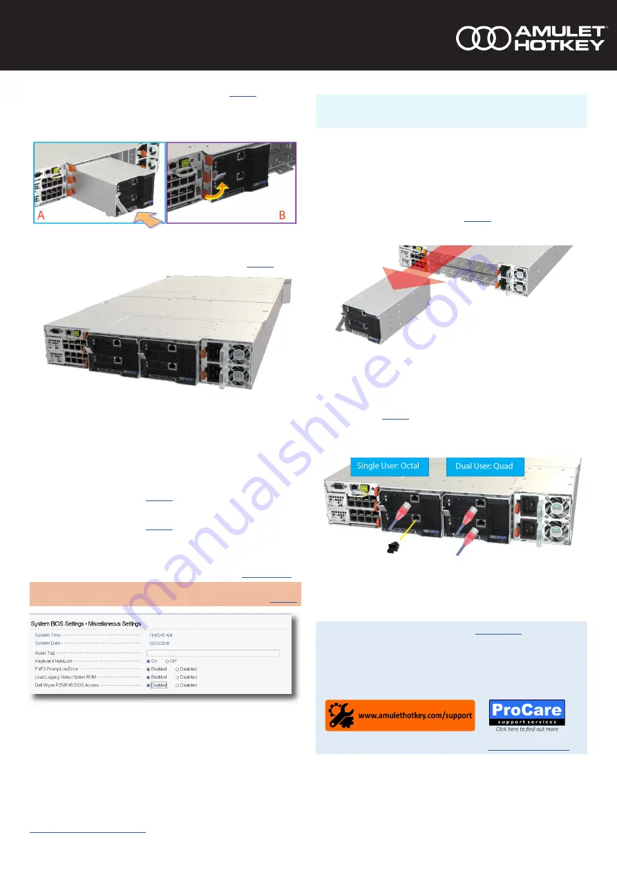
Blanking plugs
The CoreModule FX600 may or may not come fitted with a blanking plug in the
lower position. See
and make sure of the following:
Single user octal operation: fit the plug in the lower network socket.
Dual user quad operation: provide a network connection to each socket.
Figure 8:
Make sure blanking plugs are fitted correctly


