


Submersible Pumps
Drainage / Sump Series
Specifications Information and
5780-98, 5790-95, 5792-95,
Repair Parts Manual
5800-99, 5810-99 and 5811-99
Please read and save this Repair Parts Manual. Read this manual and the General Operating Instructions careful-
ly before attempting to assemble, install, operate or maintain the product described. Protect yourself and oth-
ers by observing all safety information. The Safety Instructions are contained in the General Operating
Instructions. Failure to comply with the safety instructions accompanying this product could result in personal
injury and/or property damage! Retain instructions for future reference.
5780-250-00
03/2005
Refer to form 1808-636-00 for General Operating and Safety Instructions.
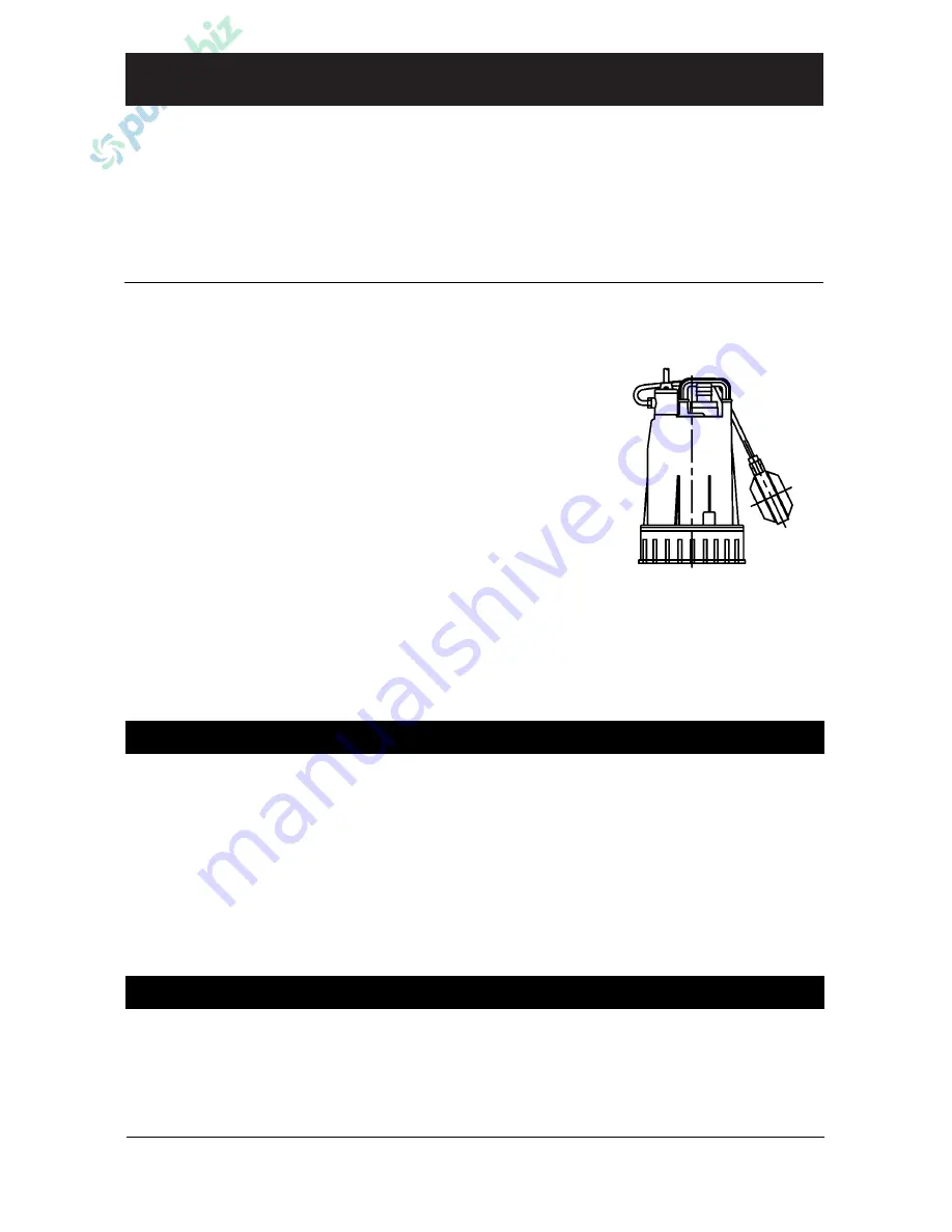
Description
These general purpose centrifugal Submersible Drainage /
Sump Pumps are intended for use in residential, commercial,
and industrial settings. Examples include: Basements, boats,
tanks, and other general drainage applications involving
clean liquids. Submersible design means low noise and no
priming issues.
Each unit is completely assembled and features a self-clean-
ing semi-open impeller and automatic on/off float switch
(stainless steel unit has no switch). All pumps incorporate a
mechanical shaft seal with carbon and ceramic wear faces.
Cast iron and SS pumps also feature a secondary shaft seal
and oil chamber.
Pumps have a 3450 RPM electric motor fitted with a finished
3-prong grounding type power cord. Motors are rated con-
tinuous duty and have automatic restart thermal overload
protection. Handle liquids from 40° to 104° F (4° to 40° C).
For use with clean, clear water and other non-flammable,
non-abrasive liquids compatible with pump component
materials.
Performance
GPM of Water at Total Head in Feet
Max.
Model
5'
10'
15'
20'
25'
30'
Head†
5800-99
15
7
—
—
—
—
14 ft.
5810-99
25
13
—
—
—
—
14
5811-99
41
30
18
3
—
—
21
5790-95
52
46
40
31
18
—
30
5792-95
62
57
50
42
34
22
37
5780-98
56
50
43
34
21
6
32
(†) Shutoff; to convert to psi, divide by 2.31
Specifications
Discharge
Power Supply
Max.
Cord
Basic
Impeller
Weight
Model
Outlet
HP
@60 Hz
Amps
Length
Const.
Material
Seals
(lbs.)
5800-99 1" HB
1/8
115VAC, 1 Phase
1.5
13'
Plastic*
Plastic
Buna N 11
5810-99 1
1
/
4
HB
1/3
115VAC, 1 Phase
3.0
13
Plastic*
Plastic
Buna N 13
5811-99 1
1
/
2
HB
1/2
115VAC, 1 Phase
4.9
13
Plastic*
Plastic
Buna N 15
5790-95 1
1
/
2
NPT
1/3
115VAC, 1 Phase
4.2
20
Cast Iron** Cast Iron Buna N 35
5792-95 2 NPT
1/2
115VAC, 1 Phase
6.9
20
Cast Iron** Cast Iron Buna N 42
5780-98 2 NPT
1/2
115VAC, 1 Phase
5.0
20
SS***
SS
Viton
26
NOTE:
Driver data is subject to change without notice, see label on driver for actual specifications.
(HB) Male Hose Barb; (NPT) Standard NPT (female) pipe thread; (SS) 304 Stainless Steel
(*) With stainless steel, brass, and plastic components.
(**) With stainless steel, brass, plastic, and plated steel components.
(***) With stainless steel and plastic components.


