


Specifications Information and Repair Parts Manual
3390-99 and 3391-99
3390-252-00.DOC 2
2/2015
3-Inch Solids-Handling Pedestal Pump
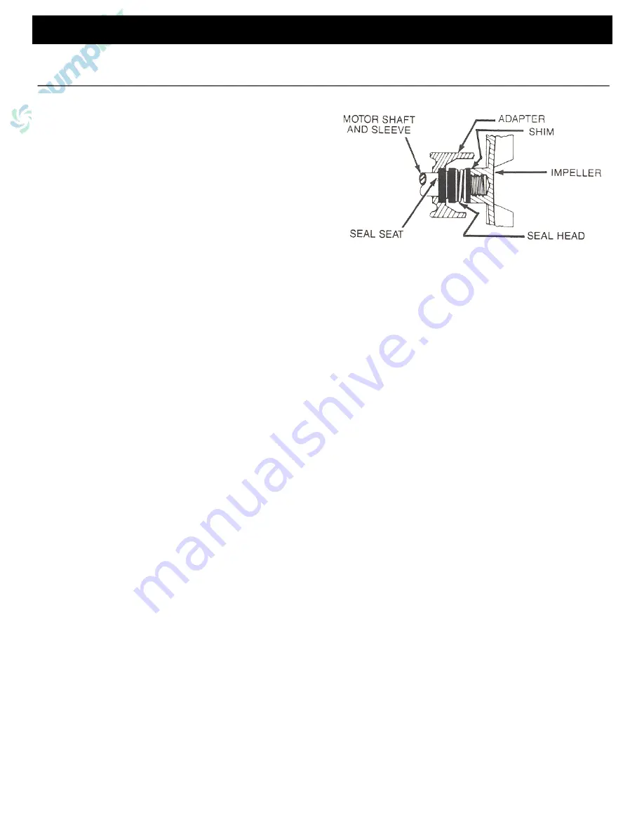
MAINTENANCE (Continued)
2.
Remove shaft sleeve with sea head on it. Separate seal head
from sleeve.
3.
Remove adapter from bearing housing (Ref. No. 14), then
using two screwdrivers or other suitable tools, remove seal
seat from adapter.
4.
Thoroughly clean all surfaces of seal seat cavity.
5.
Using a clean cloth, wipe shaft and shaft sleeve and make
certain that they are perfectly clean.
NOTE:
Do not touch or wipe polished face of seal head.
6.
Wet rubber portion of new seal seat with light coating of
soapy water. Press seal seat squarely into adapter recess.
Avoid scratching polished surface.
NOTE:
Handle all seal parts with extreme care and attention to keeping
them clean. Do not touch polished faces with your hands. Do not put
lubricants of any kind on seal faces; this can cause seal to leak.
7.
Inspect polished face of seal seat and polished face of seal
head to insure they are clean and not marred.
8.
Wet inside rubber portion of new seal head with a light
coating of soapy water. Slide head onto shaft sleeve.
IMPORTANT:
Before installing new shaft sleeve, apply a bead of non-
hardening, pliable sealant (such as Permatex® Form-A-Gasket® No. 2)
to motor shaft shoulder.
NOTE:
Reinstall any shims or spacers, which may have been removed,
onto pedestal shaft before installing impeller.
9.
Screw impeller back in place, tightening until it is against shaft
shoulder.
10.
Replace adapter, gasket and casing and fasten with eight cap
screws.
11.
After assembly, turn shaft by hand slowly to check for striking
of impeller on casing. If striking or rubbing occurs, adjust
impeller shims (see Shim Adjustment) as required.
12.
A short “run-in” period may be necessary to provide
completely leak free seal operation.
IMPELLER REPLACEMENT
Impeller (Ref. No. 6) and cutwater/wearplate (Ref. No. 3) are subject to
wear only by abrasive action of sandy or dirty fluid. If badly worn, all
these parts can be replaced easily, and pump thus restored to like-new
operation.
NOTE:
When clearance between impeller exceeds 1/16” at face of
impeller or 1/8” on outside diameter of impeller, it may be necessary to
take corrective action. The increased clearance can cause lengthened
priming times and reduced pumping capacity. If both priming and
capacity of your unit are satisfactory for your application, it is
recommended that no corrective maintenance be performed regardless
of what clearances on your unit may be developed, since the increased
clearances in themselves are not generally harmful to your pump.
Normally, new pump clearances can be restored by simply shimming
behind impeller. (Add shim washers Ref. No. 6)
If diameter of impeller is badly worn or is shim washers do not restore
clearances to less than 1/16” face dimension required, it is
recommended that impeller be replaced and refer to Figure 2.
1.
Detach pump casing (Ref. No. 2) and casing seal (Ref. No.
10)
2.
Remove two flat head socket screws (Ref. No. 4) in face of
cutwater/wearplate.
3.
Cutwater/wearplate can now be removed from casing.
4.
Simply reverse procedure to install replacement.
BEARING HOUSING SERVICE
1.
Remove front pump assembly as described under
“Mechanical Seal Replacement.”
2.
Remove shaft bearing (Ref. No. 17) and shaft (Ref. No. 18)
as an assembly by first removing snap ring (Ref. No. 20).
Push shaft bearing assembly out of bearing housing (Ref.
No. 14) by rapping on threaded end of shaft with a rawhide
mallet, or block of wood and hammer.
3.
Ball bearings can now be removed from shaft.
4.
If shaft bearings have been removed from shaft, replace by
sliding bearing on shaft to shoulder. Replace shaft bearing
assembly by sliding assembly into housing threaded end
first. Push shaft bearing assembly completely in by gently
tapping on keyway end of shaft with a rawhide mallet.
Replace snap ring.
5.
Reassemble pump as described in “Mechanical Seal
Replacement.”
SHIM ADJUSTMENT
1.
When installing a replacement impeller (Ref. No. 5) it may
be necessary to vary number of shims (Ref. No. 6) that will
be required. This is done by adding one shim more than
was removed and reassembling pump as described.
2.
Insure that casing is snugly in place and check shaft to
make sure it is turning freely. If it turns freely, check to
insure that adapter (Ref. No. 11) and casing (Ref. No. 2) are
fitted metal to metal where they meet on outside. If they are
not metal to metal, tighten cap screw (Ref. No. 12) and
recheck shaft for free turning. Tighten carefully, turning shaft
while tightening. If shaft seizes before cap screw are
completely tight, disassemble pump and remove one shim
and repeat reassembly.
3.
If at any time during above operation shaft does not turn
free or a metal to metal strike can be heard or felt when
turning shaft, follow procedure indicated above and repeat
procedure.
4.
Above procedure insures that pump will have proper
running clearance between impeller can casing and perform
like a new unit.
Figure 1- Mechanical Seal Replacement
Содержание 3390-99
Страница 4: ......


