


335A-250-00
2
3/2019
Specifications Information and Repair Parts Manual
335 Series and 336 Series
x
Diaphragm Pumps
exhaust line to the outside, regularly check the exhaust
system for leaks. Be sure the area is well ventilated.
7.
If the gas engine is equipped with a spark arrester screen in
the muffler, it should be inspected for wear periodically and
replaced when necessary.
Specific Safety Information for Electric Motor Driven
Pump
1.
This unit is not waterproof and is not intended to be used in
potentially wet locations. The motor is designed to be used in
a clean dry location with access to an adequate supply of
cooling air. Ambient temperature around the motor should not
exceed 104º F (40º C). For outdoor installations, motor must
be protected by a cover that does not block air flow to and
around the motor. This unit is not weatherproof nor is it able
to be submersed in water.
2.
When wiring an electrically driven pump, follow all electrical
and safety codes, as well as the most recent United States
National Electrical Code (NEC) and the Occupational Safety
and Health Act (OSHA).
Risk of electrical shock! Never connect the green (or green and
yellow) wire to a live terminal.
3.
To reduce the risk of electric shock, the motor must be
securely
and
adequately
grounded!.
This
can
be
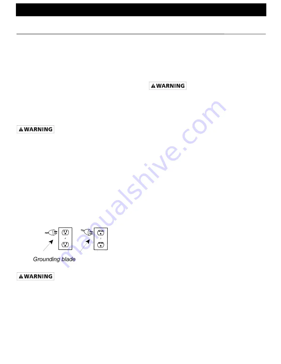
accomplished by either: (1) inserting plug (portable) directly
into a properly installed and grounded 3-prong grounding-type
receptacle (as shown in Figure 2); (2) permanently wiring the
unit with a grounded metal raceway system; (3) using a
separate ground wire connected to the bare metal of the
motor frame; or (4) other suitable means. The green (or green
and yellow) conductor in the cord is the grounding wire. The
motor must be securely and adequately grounded for your
protection against shock hazards! Where a 2-prong wall
receptacle is encountered, it must be replaced with a properly
grounded 3-prong receptacle with a grounded 3-prong
receptacle installed in accordance with the National Electrical
Code and local codes and ordinances. To ensure a proper
ground, the grounding means must be tested by a qualified
electrician. Use only 3-wire extension cords that have 3-
prong, grounding-type plugs and 3-pole receptacles that
accept the equipment plug.
4.
All wiring should be performed by a qualified electrician.
Figure 2 Grounding Methods
An incorrect connection may cause an electric short, produce an
electrical shock or burn out the pump motor, resulting in property
damage and/or personal injury.
5.
Protect electrical cord from sharp objects, hot surfaces, oil
and chemicals. Avoid kinking the cord. Replace or repair
damaged or worn cords immediately.
6.
Provide safety shields on all moving and electrical parts to
prevent personal injury.
7.
Keep fingers and foreign objects away from ventilation and
other openings. Do not insert any objects into the motor.
8.
Use wire of adequate size to minimize voltage drop at the
motor.
9.
Disconnect power before servicing a motor or its load. If the
power disconnect is out of sight, lock it in the open position
and tag it to prevent unexpected application of power.
10.
Do not touch an operating motor. Modern motors are
designed to operate at high temperatures.
General Safety Information (All Units)
1.
Know the pump application, limitations and potential
hazards.
Do not use to pump flammable or explosive fluids such as
gasoline, fuel oil, or kerosene, etc. Do not use in flammable
and/or explosive atmospheres. Pump should only be used with
liquids compatible with pump component materials. Failure to
follow this warning can result in personal injury and/or property
damage.
2.
Make certain that the power source conforms to the
requirements of your equipment.
3.
Provide adequate protection and guarding around moving
parts.
4.
Disconnect power before servicing.
5.
Release all pressure within the system before servicing any
component.
6.
Drain all liquids from the system before servicing.
7.
Secure the discharge line before starting the pump. An
unsecured discharge line will whip, possibly causing
personal injury and/or property damage.
8.
Check hoses for weak or worn condition before each use,
making certain that all connections are secure.
9.
Periodically inspect pump and system components. Perform
routine maintenance as required (see Maintenance
Section).
10.
Provide a means of pressure relief for pumps whose
discharge line can be shut off or obstructed.
11.
Personal Safety:
a.
Wear safety glasses at all times when working
with pumps.
b.
Wear a face shield and proper apparel when
pumping hazardous chemicals.
c.
Keep work area clean, uncluttered and properly
lighted - replace all unused tools and equipment.
d.
Keep visitors at a safe distance from the work
area.
e.
Make workshop childproof
– with padlocks,
master switches and by removing starter keys.
12.
For air drive units follow Safety Information in instruction
sheet supplied with air motor.
.
ASSEMBLY
1.
HANDLE ON 2" PUMP
(Refer to Figure A)
a.
Remove two hex cap screws (Ref. No. A6) and
washers (Ref. No. A7) from gearbox (Ref. No.
A1).
b.
Place handle (Ref. No. A35) on gearbox flange
and align holes.
c.
Reinstall two hex cap screws and washer
assemblies, then tighten.
HANDLE ON 3" PUMP
(Refer to Figure A)
d.
Remove two hex nuts from pump well (Ref. No.
A3).
e.
Place handle (Ref. No. A35) under pump well.
f.
Reinstall two hex nut and washer assemblies,
then tighten.
2.
ROTATING SUCTION/DISCHARGE PORTS (OPTIONAL)
(Refer to Figure A,W,P)


