


E. Start up procedures
1. Check that all fittings and hoses are securely attached, and that the
hoses are routed properly.
2. Check engine oil level. Fill to full mark if necessary.
3. Set vehicle parking brake, With transmission in park/neutral start the
engine and immediately check oil pressure. Note: Pressure may initially
take a moment or two to rise.
Caution:
Carefully check for leaks at fittings, hoses and mount. If leaks
are observed,
STOP ENGINE IMMEDIATELY
, repair leaks and continue.
4. After engine has warmed, shut off and re-check engine oil level. Fill as
necessary.
5. Record vehicle mileage/operating hours and date of installation.
F. Periodic maintenance
1. Periodic visual inspection of the fittings and hoses is recommended. Look
for leaks, hose deterioration and cuts. Repair and/or replace as necessary.
2. To change the filter element:
a. Ensure engine is off and use caution as the engine, oil and filter may
be hot and could result in an injury.
b. Using a filter wrench, remove the filter elements. Dispose of properly.
c. Clean the filter gasket contact areas on the mount with a clean, lint-
free rag.
d. Lubricate the new filter gaskets with clean oil or grease.
e. Fill filters as full as possible with engine oil.
f. Screw on new filters, tighten per instructions on filter can.
g. Start engine and check for leaks.
h. Check engine oil level, fill as needed.
3. Record vehicle mileage/operating hours for future reference.
Diesel Powered Engines:
Due to higher oil contamination levels in diesel
engines and variance in fuel quality, maintenance intervals for the filter ele-
ment and oil change intervals should be determined using oil analysis. For
more on oil analysis see the last page.
8
7
9
10
11
7
6
11
7
1
6
8
7
OUT
IN
17
16
2
12
15
5
13
4
14
14
14
3
3
3
14
4
5
EaBP-100
10
″
10
1
⁄
4
″
Ea0-26
5
″
9
″
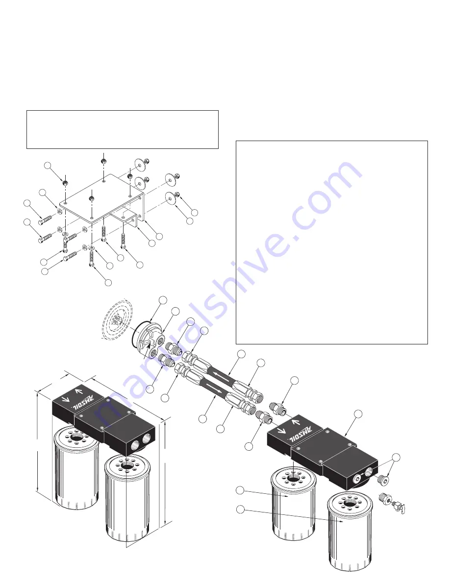
Diagram A
MINIMUM AREA NEEDED FOR
DUAL MOUNT AND SPIN-ON OIL FILTER ELEMENTS
* Mount and element heights plus 1-inch removal clearance
Parts and assembly list
Item
Description
Qty.
Part No.
1.
Filter Mount Assembly
1
BK-209
2.
Allen Head Plug
2
BP-191
3.
1
⁄
4
20 x 1
Hex Head Bolt
4
BP-23
4.
1
⁄
4
I.D. Washer
6
BP-21
5.
1
⁄
4
-20 Self Locking Nuts
8
BP-22
6.
Adapter Fitting
1
⁄
2
NPT-
1
⁄
2
JIC
2
BP-201
7.
Hose Fitting
4
BP-260
8.
13
⁄
32
I.D. Hose
8
BP-250
9.
Spin-On Casting (Cummins) with “O” ring
1
BP-176
Spin-On Casting (International) with “O” ring
1
BP-177
Spin-On Casting (Duramax) with “O” ring
1
BP-219
10.
“O” Ring 2
1
⁄
2
I.D. (Cummins, Duramax)
1
BP-161
“O” Ring 3
5
⁄
8
I.D. (International)
1
BP-178
“O” Ring 3
1
⁄
8
I.D. (Duramax)
1
BP-162
11.
“O” Ring Fitting Adapter
3
⁄
4
-16 x
1
⁄
2
JIC
2
BP-189
12.
Mounting Bracket (top)
1
BP-194
13.
Mounting Bracket (bottom)
1
BP-195
14.
1
⁄
4
-20 x 1
1
⁄
2
Hex Head Bolt
4
BP-185
15.
1
⁄
4
I.D. Fender Washer
4
BP-186
16.
Full-Flow Filter
1
EaO-26
17.
By-Pass Filter
1
EaBP-100
Plastic Tie
2
BP-46
Thread Sealant
1
BP-198
Instruction Sheet
1
BP-174
Optional Parts Available From AMSOIL INC.
90° Fitting, Pack of 2
BK-11
45° Fitting, Pack of 2
BK-12
Oil Sampling Kit
BK-13
Diagram B
BMK-15 Ea, 16 Ea,
and 17 Ea
or optional
BK-13 Sampling
Kit
AMSOIL
By-Pass Filter
EaBP-100
AMSOIL
Full-Flow Filter
EaO-26
Red
Indicator
BP174 83642 8/23/06 8:22 AM Page 2


