5
Installation :
Step 1:
Wall or shelf mount the unit. Screws and rubber feet are supplied in the accessory kit.
Step 2:
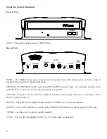
Verify that the power switch on rear of unit is set to OFF. Attach the included power pack to a wall or
power strip receptacle, then attach the other end to the jack on the rear of the unit labeled 15VDC.
Step 3
: If connecting unit to an amplifier make sure it is turned OFF for this part of the installation.
Step 4:
Connect a RCA cable (supplied in the accessory kit) to the OUTPUT jack on the rear of the unit. Depending
upon the required impedance use either the 8Ω or 600Ω output RCA jack. Connect the other side to an MOH port,
PA system or speaker.
Step 5:
Turn the power switch on rear of unit to the ON position. After the unit initializes the STATUS LED on the
rear of unit will turn either SOLID GREEN if a message has been pre-loaded and is playing, or BLINK GREEN
if no message is present. This process may take up to 30 seconds.
Step 6:
If a message needs to be loaded then follow the loading instruction in this manual.
Step 7:
Slide the SPEAKER switch located on the rear of the unit to the ON position. This speaker is for verifying
audio playback and testing purposes only – DO NOT use this for setting the OUTPUT volume level!
Step 8:
If any amplifiers or monitors were turned OFF during installation turn them back ON now.
Step 9:
Adjust the volume level pot labeled VOLUME on the rear of the unit in conjunction with the monitor or
amplifiers master volume to achieve a balanced but not over driven audio level.
Step 10:
Slide the SPEAKER switch to the OFF position and installation is complete.
POWER
15VDC
1.67A
ON
OFF
STATUS
SPEAKER
ON
OFF
RESET
VOLUME
OUTPUT
8Ω
600Ω
OR
Wiring Diagram


