12
ACD-20SW
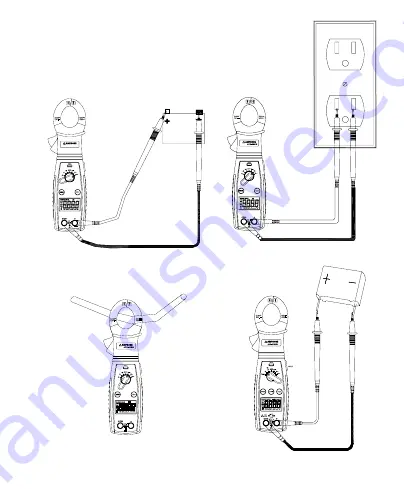
Fig.3 Measuring AC Current
Fig.4 Measuring Capacitance
Fig.2 Measuring AC Voltage
Fig.1 Measuring DC Voltage
Страница 1: ...Users Manual ACD 20SW ACD 21SW ACD 21SWC Digital Clamp Meter For detailed specifications and ordering info go to www TestEquipmentDepot com ...
Страница 2: ...ACD 20SW ACD 21SW ACD 21SWC Digital Clamp Meter Users Manual September 2009 Rev 2 2009 Amprobe Test Tools All rights reserved Printed in Taiwan English ...
Страница 3: ...xclusion or limitation of an implied warranty or of incidental or consequential damages this limitation of liability may not apply to you Repair All test tools returned for warranty or non warranty repair or for calibration should be accompanied by the following your name company s name address telephone number and proof of purchase Additionally please include a brief description of the problem or...
Страница 4: ... 7 Common Ground reference Input jack for all functions EXCEPT clamp on ACA current function 8 Input jack for all functions EXCEPT clamp on ACA current function 9 NCV Push button function 10 NCV Sensor 11 Hand Finger Barrier to indicate the limits of safe access of the meter during measurement 12 Hold Push button function 13 Ohm Continuity push button function 14 Input jacks for temperature measur...
Страница 5: ... 6 Continuity Testing 6 Diode Testing ACD 20SW 7 Temperature Measurement ACD 21SW ACD 21SWC only 7 Non Contact Voltage Indicator 7 Auto Power off 8 Cancellation of Auto Power off feature 8 SPECIFICATIONS 8 DC Volts 9 AC Volts 9 AC Current 9 Resistance 9 Capacitance ACD 21SW ACD 21SWC only 10 Temperature ACD 21SW ACD 21SWC only 10 Continuity 10 NCV Non Contact Voltage Indicator 10 Diode Test ACD 20...
Страница 6: ...pliance This instrument is EN61010 1 certified for Installation Category III 600V It is recommended for use in primary supply lines overhead lines and cable systems and distribution level and fixed installations as well as lesser installations Do not exceed the maximum overload limits per function see specifications nor the limits marked on the instrument itself Never apply more than 600 V ac rms ...
Страница 7: ...e using the instrument If any defects are found replace them immediately This Clamp on meter is designed to apply around or remove from un insulated hazardous live conductors Individual protective equipment must be used if hazardous live parts of the installation could be accessible Exercise extreme caution when measuring voltage 20 V current 10 mA AC power line with inductive loads AC power line ...
Страница 8: ...t or inconvenient to reach places Simply rotate the body of the meter to get an unobstructed view of the LCD display Rich set of features and CAT III 600V safety reading for use in electrical and HVAC applications The features include 180 degree rotating head for the perfect display viewing Advanced VoltTect non contact voltage detection Slim jaw design with one hand operation Measures AC Current ...
Страница 9: ...3 Connect the test probes to the circuit test points Refer to Fig 1 4 Read the display If necessary correct any overload 0L conditions Measuring AC Voltage 1 Set the Function Switch to K 2 Connect the test leads Red to Black to COM 3 Connect the test probes to the circuit test points Refer to Fig 2 4 Read the voltage on the primary display and the frequency on the secondary display If necessary co...
Страница 10: ...tch to e Use the e R button to select the resistance test ACD 21SW ACD 21SWC only 2 Connect the test leads Red to Black to COM 3 Turn off power to the circuit being measured Never measure resistance across a voltage source or on a powered circuit 4 Discharge any capacitors that may influence the reading 5 Connect the test probes across the resistance Refer to Fig 5 6 Read the display If 0L appears...
Страница 11: ...tion Insert the thermocouple plug matching the slot widths 4 Connect the thermocouple bead to the test point Refer to Fig 6 5 Read the display If 0L appears on the display the temperature is too large to be measured or the thermocouple is open 6 ACD 21SW Fahrenheit ACD 21SWC Celsius 7 Setting up for 400 C or 400 F measurements Open bottom case and find the jumper next to jack on 400 C when the jum...
Страница 12: ...nge OL or OL is displayed Zero Automatic Low battery indication The is displayed when the battery voltage drops below the operating level Measurement rate 2 times per second nominal Auto power off Approx 10 minutes Operating environment 0 C to 50 C 32 F to 122 F at 70 relative humidity Storage temperature 20 C to 60 C 4 F to 140 F at 80 relative humidity Accuracy Stated accuracy at 23 C 5 C 75 rel...
Страница 13: ... to 400V ranges 600V 1mV 1 5 rdg 5 dgts on 600V range Input impedance 4V 10Me 40V 600V 9 1Me Overload protection 600VDC or AC rms AC Current 50Hz 60Hz Ranges Resolution Accuracy 40A 400A 0 01A 2 0 rdg 6 dgts Overload protection 400AAC Resistance Ranges Resolution Accuracy 400e 4ke 40ke 400ke 0 1e 1 0 rdg 4 dgts 4Me 0 1e 1 5 rdg 4 dgts 40Me 0 1e 3 0 rdg 5 dgts Open circuit volts 0 45V dc typical 1 ...
Страница 14: ... and need to be discharged before testing Overload protection 600VDC or AC rms Temperature ACD 21SW ACD 21SWC only Range 35 C 400 C 30 F 400 F Resolution 0 1 F 0 1 C Accuracy 1 0 2 F 32 F 400 F 1 0 1 C 0 C 400 C 2 0 6 F 30 F 32 F 2 0 3 C 35 C 0 C Sensor type K type thermocouple Overload protection 30V Max Continuity Range 400e Resolution 1e Audible indication Less than 25e Response time 500ms Over...
Страница 15: ...e a malfunction during the operation of the meter the following steps should be performed in order to isolate the cause of the problem 1 Check the battery Replace the battery immediately when the symbol appears on the LCD 2 Review the operating instructions for possible mistakes in operating procedure Except for the replacement of the battery repair of the meter should be performed only by a Facto...
Страница 16: ...12 ACD 20SW Fig 3 Measuring AC Current Fig 4 Measuring Capacitance Fig 2 Measuring AC Voltage Fig 1 Measuring DC Voltage ...
Страница 17: ...13 ON ON ON ON ON ON OFF OFF OFF OFF OFF OFF OFF OFF OFF OFF OFF OFF Fig 7 Non Contact voltage NCV Measurement Fig 6 Measuring Temperature Fig 5 Measuring Resistance ...