
9
Temposonics
®
GB-Series SSI
Operation Manual
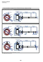
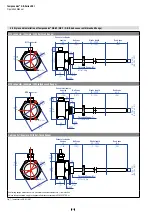
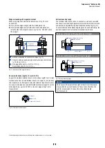
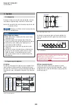
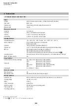
Installation of GB with pressure fit flange
Mount the sensor via pressure fit flange through the bores in the
sensor electronics housing with 6 machine screws M6×16 A2-70
(ISO 4762).
Fig. 4:
Installation of GB with pressure fit flange »S« & »N«
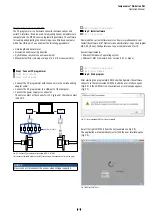
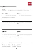
Fig. 5:
Sensor in cylinder
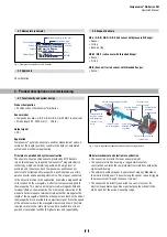
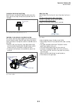
Installation of a rod-style sensor in a
hydraulic
cylinder
The rod-style version has been developed for direct stroke measure-
ment in a
hydraulic
cylinder. Mount the sensor through the bores in
the sensor electronics housing with 6 machine screws M6×16 A2-70
(ISO 4762).
• Mounted on the face of the piston, the position magnet travels
over the rod without touching it and indicates the exact position
through the rod wall – independent of the hydraulic fluid.
• The pressure resistant sensor rod is installed into a bore in the
piston rod.
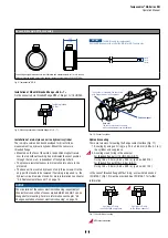
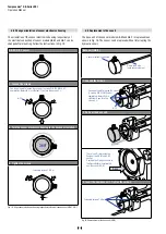
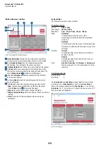
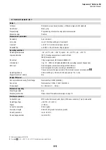
Hydraulics sealing
Seal the flange contact surface via O-ring in the undercut as shown in
For pressure fit flange Ø18 f7 (GB-K / GB-N / GB-S):
O-ring 15 × 2 mm (0.59 x 0.02 in.) (part no. 560 853)
For pressure fit flange Ø21 f6 (GB-J):
O-Ring 17 × 2 mm (0.67 x 0.02 in.) (part no. 561 438)
Fig. 6: Sealing
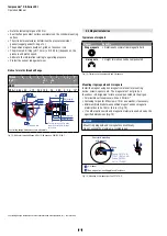
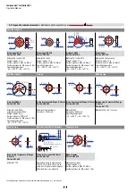
•
Note the fastening torque of machine screws of 6 Nm.
•
Seat the flange contact surface completely on the cylinder mounting
surface.
• The cylinder manufacturer determines the pressure-resistant
gasket (copper gasket, O-ring, etc.).
• The position magnet should not grind on the sensor rod.
•
The piston rod drilling (GB-N / GB-S: ≥ Ø 13 mm (≥ Ø 0.52 in.),
GB-J / GB-K: ≥ Ø 16 mm (≥ Ø 0.63 in.)) depends on the pressure
and piston speed.
• Adhere to the information relating to operating pressure.
• Protect the sensor rod against wear.
Fastening torque
6 Nm
Sensor electronics housing
with sensor rod
Position magnet
Sealing via O-ring
in the flange undercut