


20
Temposonics
®
GB-Series SSI
Operation Manual
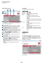
Fig. 29:
User interface GB Serial Configurator
GB SSI software user interface
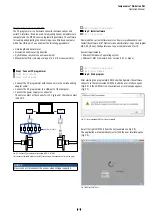
1
Sensor Information
contains the invariable sensor parameters,
which were read in automatically when the sensor is connected.
2
In the
Device Settings
menu the configurable parameters
(SSI Settings, Error Settings) of the sensor can be set.
3
The
Measurement
menu shows the current position of the magnet.
4
The
Save
button saves any parameter changes you have made.
After that the software restarts for the changes to take effect. The
function
Measurement
3
will then be available again.
5
The button
Disconnect
breaks the connection to the COM Port
and closes the software.
6
By clicking
Report
a report document is generated to provide
sensor information.
7
The
File
menu allows the following settings (see also Fig. 29):
1.
Open
: Uploads device settings from a XML file to the sensor.
Click the
Save
button
4
to complete the upload
2.
Save as
: Saves the current device settings as XML file
3.
Restore Factory Settings
: Restores and saves the sensor’s factory
settings
4.
Close
: Closes the software application without saving any
parameters
Device Settings
The following parameters can be modified:
SSI Settings (Fig. 29)
Format:
Binary
/
Gray
Data Length:
24 bits
/
25 bits
Resolution:
5 µm
/
10 µm
/
20 µm
/
50 µm
/
100 µm
Mode:
Asynchron
:
In asynchronous mode the sensor starts
measuring and provides the position independent
of the PLC.
Synchron
:
In synchronous mode the output of the Temposonics
®
SSI sensor is matched to the data request cycle of the
controller.
Direction:
Forward
:
Ascending position values from sensor electronics
housing to rod end
Reverse
:
Ascending position values from rod end to sensor
electronics housing
Filter:
No Filter
/
Filter Avg. 2
/
Filter Avg. 4
/
Filter Avg. 8
:
Moving average of 2, 4 or 8 measurements for noise
reduction
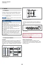
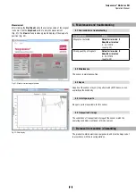
Error Settings (Fig. 30)
Error Counter:
1
Error Value:
0
The
Error Counter
and
Error Value
settings determine, how often an
error has to occur (
Error Counter
) so that a certain
Error Value
is
shown. The standard settings for the
Error Counter
is “1” and for the
Error Value
it is “0”. So every error is shown with an error value of “0”.
Both parameters are changeable.
Fig. 30: Error Settings
1
2
3
4
5
6
7