background image

Содержание MM-1200

Страница 1: ...imer Accessory Transport Control Assembly Motor Drive Amplifier Assembly Head Assembly Electronics Assembly Control Box Assembly Meter Panel Assembly Power Supply Optional Equipment Specifications SECTION 2 INSTALLATION Equipment Siting Unpacking Power Requirements Cable Connections Initial Adjustments Input Signal Setup Balanced Line Unbalanced Line Output Signal Setup Balanced Output Unbalanced ...

Страница 2: ... OF OPERATION General Audio Electronics Record Reproduce Individual Channel Audio Switching INPUT REPRO S SYNC Switch Circuit Sync Transfer Switch Audio Mute Function Record Function Master and Standby Monitor Audio Switching STANDBY MONITOR Switch Circuit MASTER MONITOR Switch Circuit LIFT DEFEAT Switch Circuit READY SAFE Switch Circuit Status Display Circuits TAPE SPEED Switch Circuit MASTER MON...

Страница 3: ...ic Record Logic Fast Forward Logic Rewind Logic Tape Tension Control and Servo Tension Error Amplifier Play Record Mode Rewind Mode Fast Forward Stop End of Tape Search to Cue and Tape Timer Tape Timer Search to Cue Reel Motor Drive Amplifiers Capstan Servo Block Diagram Description Circuit Description Power Supply 39 Vdc Regulator Bias Oscillator 27 Vdc Regulator 15 Vdc Regulator 5 Vdc Regulator ...

Страница 4: ...t Regulator Adjustment Motor Drive Amplifier Transport Control Preliminary Setup Tension Sensor Arm Calibration Normalizing Reel Servos Tension Adjustments Capstan Servo System Search to Cue Tape Timer Checkout Adjustment Alignment of Photo Isolators Mechanical Adjustments Takeup Reel Brake Adjustment Brake Check and Adjustment Brake Solenoid Air Damping Supply Reel Brake Adjustment Capstan Servo ...

Страница 5: ...of Distortion Causes of Flutter Flutter Troubleshooting Hints Transport Control Audio Switching Audio Signal Reproduce Amplifier Record Amplifier Bias Amp Module Power Supply Removal and Replacement Control Box Assembly Disassembly Toggle Switch Removal and Replacement Pushbutton Switch Removal and Replacement LE D Removal and Replacement Reassembly Reel Motors Capstan Motor Head Assembly Tension ...

Страница 6: ...6 PARTS LISTS AND SCHEMATICS Indentured List of Assemblies Numerical List of Assemblies Numerical List of Schematics APPENDIX A Integrated Circuits APPENDIX B Transport Control PWA 4050706 Alignment PAGE NO 6 ii 6 vi 6 ix A 1 8 1 AMPEX 4890400 02 ...

Страница 7: ...ematic S Sync and Repro Signal Path Partial Schematic Audio Control Partial Schematic _ Divider Voltages with Neutral Control Signal REPRO Divider Voltages with 27V Control Signal S SYNC Divider Voltages with Ground Control Signal I NPUT Control Panel Simplified Schematic Channel 1 Shown Stop and Braking Logic Partial Schematic Play and Record Logic Partial Schematic Fast Forward and Rewind Logic ...

Страница 8: ...eamplifier Adjustment Waveforms With Tape Moving in the Forward Direction Transport Adjustment Points Servo Motor Maintenance Tape Lifter Adjustment Pinch Roller Adjustment End of Tape Arm Tension Arm Dashpot Assembly End of Tape Arm and Threading Switch Adjustment 30 Hz to 18 kHz Band Limiting Filter ASA A Weighted Filter Control Box Case Removal Control Box Assembly Switch PWA Disassembly Switch...

Страница 9: ... Operator Controls for a Typical Channel Line Output Monitor Signals Audio Switching Bus Levels High Frequency Equalization Components Test Equipment and Maintenance Materials Transport Brake Torques Electronics Assembly Alignment Adjustments Ampex Alignment Test Tapes Rotational Rates Revolutions Second Troubleshooting Hints Transport System Troubleshooting Hints Audio Switching System Troublesho...

Страница 10: ...13550 1 MM 1200 Multichannel Recorder Reproducer 1 0 AMPEX 4890400 02 ...

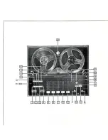
Страница 11: ...embly audio electronics assemblies a control box assem bly a power supply assembly a meter panel Ampex Trademark AMPEX 4890400 02 assembly an accessory panel and an input output panel assembly Multi pin connectors are used extensively between units to facilitate removal and replacement of various components and assemblies Location of the various components and assemblies are shown in Figures 1 1 a...

Страница 12: ...ith ball bearings at each end of the roller shaft An adjustable pressure spring is used to maintain the correct force of the pinch roller against the capstan 1 2 1 6 Tension Sensor Assembly The tension sensor assembly adjacent to the supply reel assembly consists of two photovoltaic cells and an incandescent lamp mounted on a fixed bracket The three active components are wired to a connector plug ...

Страница 13: ... adjacent to the takeup reel is contained in a housing and consists of a spring loaded tension arm fitted with a tape guide at the free end The AMPEX 4890400 02 post to which the tension arm is attached extends through the transport chassis and is mechanically coupled to a dashpot assembly to damp the motion of the spring loaded arm The end of tape arm is equipped with an actuator that activates a...

Страница 14: ...s in the standby mode and in the play and record modes of operation 1 4 1 9 Search to Cue Tape Timer Accessory The tape timer consists of a tape driven idler attached to a mounting housing The timer idler roller drives a disc that has alternate opaque and transparent segments As this disc rotates caused by tape motion it interrupts light sources that are focused on a pair of photosensitive diodes ...

Страница 15: ...s of a multi pin connector to the main transport control harness of the MM 1200 There is sufficient slack in the wiring harness such that the entire MDA assembly may be removed for servicing Figure 1 5 shows the MDA assembly and the MDA printed wiring assembly 1 12 HEAD ASSEMBLY Eight track 16 track and 24 track head assemblies are available for use with the MM 1200 in the standard configuration T...

Страница 16: ...oard adjacent to the reproduce amplifier connector socket and are accessible with the record amplifier removed 1 6 Each group of units i e audio switcher repro duce amplifier record amplifier and bias amp module is associated with one audio channel Therefore if the MM 1200 has an 8 track capa bility two complete electronic assemblies are required Four electronic assemblies would be required for a ...

Страница 17: ...rder Repro9ucer with the exception of four audio controls located on the electronics assembly The transport control switches are all of the illuminated pushbutton type except AMPEX 4890400 02 the TAPE SPEED switch which is a two position toggle Depressing any pushbutton switch except RECORD and LIFT DEFEAT cancels any push button switch previously selected The RECO RD pushbutton switch has no effe...

Страница 18: ...RIDGING _____ TRANSFORMER MOTHERBCJARD AUDIO SWITCHER M DULE BIAS AMP MODULE AMPLIFIER REPRODUCE AMPLIFIER Figue 1 7 Electronics Assembly Typical Figure 1 8 Control Box Assembly 13550 21 14245 3 AMPEX 4890400 02 ...

Страница 19: ...PWAs and their associated power transistors provide 39 volt 27 volt and 15 volt power for the transport assembly electronics assemblies and the bias oscillator The 5 volt regulator mounted on the heatsink provides power to the search to cue tape timer assembly The bias oscillator which is a part of the 39 volt regulator PWA provides bias current to all the bias amp modules The 39V and the 15 27V P...

Страница 20: ...er Supply Table 1 1 Optional Equipment PART NO USE 4850154 Converts from 2 inch to 1 inch capability 4210353 01 02 Auxiliary 1 or 2 inch guide 4020334 Converts from 16 track to 8 track capability 4020372 Converts from 24 track to 16 track capability 4010246 Converts to 16 track capability 4010247 Converts to 24 track capability 4952348 02 Provides remote capability for control box assembly 4010268...

Страница 21: ...onization at shuttle speeds Search to Cue Timer Remote Display 4020410 02 Provides remote control of search to cue Accessory function and timer display Transformer 4580200 02 Permits use of 600 ohm balanced line Overhead Bridge Assembly 4010242 02 Permits mounting of accessory equipment such as Auditec Sync Lock and Synchronizer 2 lnch Tape Splicer Accessory 4010249 01 Facil itates tape splicing S...

Страница 22: ... in s 2 dB from 40 Hz to 15 kHz not applicable to Sel Sync mode 15 in s 2 dB from 30 Hz to 15 kHz 30 in s 2 dB from 50 Hz to 18 kHz Signal to Noise Ratio Using Ampex 456 tape or equivalent at 7 1 2 15 or 30 in s Using Ampex 406 tape or equivalent at 7 1 2 15 or 30 in s Third Harmonic Distortion 7 1 2 15 or 30 inls 1000 Hz 8 or 16 channel 64 dB 24 channel 59 dB peak record level to unweighted 30 Hz...

Страница 23: ...ute record time for tape recorded rewound and reproduced on the same unit Electronic Tape Timer Tape driven Reads up to 1 hour 59 minutes 59 seconds at any play speed Search to Cue Bidirectional Searches either direction to a preset cue point Tape Speed Accuracy Within 0 05 from beginning to end of reel per NAB Standard on Magnetic Recording and Reproduction 1965 Section 2 02 01 Capstan Reference ...

Страница 24: ...00 16 Channel MM 1200 24 Channel 0 8 kVA maximum 1 0 kVA maximum without accessories 1 2 kVA maximum Size 8 16 and 24 track units without overhead bridge Weight 1 14 Width Depth Height 8 Track 16 Track 24 Track 29 in 74 cm 27 in 69 cm 45 in 114cm 415 Ib 188 kg 465 Ib 210 kg 530 Ib 240 kg AMPEX 4890400 02 ...

Страница 25: ... inspect each record and reproduce amplifier and check that the equalizer plug in PWAs have not become dislodged during shipment Check that the audio switcher and the bias amp module PWAs have not become dislodged during shipment 2 3 POWER REQUIREMENTS The MM 1200 requires 115 220 volts at 50160 Hz nominal Power is connected by a grounding type three prong plug AMPEX 4890400 02 WARNING ENSURE THAT...

Страница 26: ...quired usage 2 5 INITIAL ADJUSTrv1ENTS 2 6 Input Signal Setup The MM 1200 Recorder Reproducer is provided with a line bridging transformer for each channel Four of these line bridging transformers are mounted on the rear of each electronics assembly These transformers provide a 20 kilohm balanced input to each record amplifier An accessory input transformer Ampex Part No 4580200 02 can be used in ...

Страница 27: ...lect the desired position of the SYNC TRANSFE R switch for the installation The REPRO position away from the transport selects the record head as the monitor source Sel Sync monitor function for all channels set to S SYNC The INPUT AMPEX 4890400 02 position toward the transport selects the record input as the monitor source for all channels selected to S SYNC 2 13 Speed Selection 2 14 Fixed Speed ...

Страница 28: ... timer PWA Figure 2 4 position the speed straps as follows Table 2 3 Tape Speeds for Various Input Frequencies 1 Remove power from the recorder reproducer and remove the search to cue and tape timer PWA from the transport control chassis TAPE SPEED INPUT FREQUENCY Hz 1 4 speed 2400 1 2 speed 4800 Normal 9600 Normal speed Is determined by the setting of the TAPE SPEED switch on the control box and ...

Страница 29: ...LO SPEED JUMPER HI SPEED JUMPER AMPEX 4890400 02 Figure 2 4 Search to Cue and Tape Timer PWA R49 R51 R54 13540 10 2 5 ...

Страница 30: ...istor R51 and replace it with a 68K 1 4 watt 5 composi tion type resistor 2 6 2 Remove 36K resistor R54 and replace it with a 20K 1 4 watt 2 metal film resistor 3 Remove 130K resistor R49 and replace it with a 110K 1 4 watt 2 metal film resistor 4 Perform the checkout and adjustment pro cedures outlined in paragraphs 5 22 and 5 23 AMPEX 4890400 02 ...

Страница 31: ...stan servo PWA and the search to cue tape timer PWA in the transport control chassis as described in paragraphs 2 13 and 2 16 AMPEX 4890400 02 3 5 Variable Speed Mode To operate the system at variable speeds using Ampex VS 10 Variable Speed Oscillator remove the dummy plug from the VARIABLE SPEED connector located on the accessory panel and connect the VS 10 electrical connector in its place The V...

Страница 32: ...sition sets the control circuitry to select the audio input to the machine as the output signal for that channel The REPRO position sets the control circuitry to select the reproduce head for that channel as the signal source while in the normal reproduce or the record mode The S SYNC position sets the control circuitry to select the record head for that channel for use as a reproduce head while t...

Страница 33: ... configuration the MASTER MONITOR switch has selected i e REPRO SINGLE or S SYNC With the STANDBY MONITOR switch in the SINGLE position the outputs selected will be determined by the position of the individual INPUT REPRO S SYNC switches same as SINGLE position of MASTER MONITOR switch When illuminated shows that the control circuitry to select the position of the INPUT REPRO S SYNC switches as a ...

Страница 34: ...ps tape movement and causes the control circuitry and signal electronics to enter the standby mode of operation This switch illuminates when depressed and re mains illuminated during the standby mode In the edit mode the STOP indicator is extinguished when LIFT DEFEAT is operated to release the reel brakes but illuminated when STOP is pressed to re apply the reel brakes This switch when depressed ...

Страница 35: ...ing SEARCH When illuminated these indicators show in and hours minutes and seconds the distance the tape has moved from timer zero indication This switch selects the cue point for the search to cue function Table 3 3 Electronics Assemblies Operator Controls for a Typical Channel DESCRIPTION BIAS AUDIO toggle switch FUNCTION This switch selects the input to the vu meter for that channel The AUDIO p...

Страница 36: ...rol permits adjustment of the reproduce audio level from the reproduce head for its associated channel during the normal reproduce mode Table 34 Line Output Monitor Signals SWITCH POSITION MODE MASTER INDIVIDUAL RECORD PLAY STANDBY MONITOR CHANNEL STOP FF or REW REPRO INPUT REPRO REPRO REPRO REPRO REPRO REPRO REPRO S SYNC REPRO REPRO REPRO SINGLE INPUT INPUT INPUT INPUT REPRO REPRO REPRO REPRO S S...

Страница 37: ...Figure 3 1 close the head gate and release the end of tape arm 5 On the control box assembly set the TAPE SPEED switch to the desired speed 6 Set the STANDBY MONITOR switch to SINGLE 7 Set the individual INPUT REPRO S SYNC switches to the INPUT position the same channel READY SAFE switches to the READY position and all other READY SAFE switches to the SAFE position AMPEX 4890400 02 8 Set the BIAS ...

Страница 38: ...oring one channel while recording on another finishes with the newly re corded track slightly behind the previously re corded track See the center diagram of Figure 3 2 This problem is resolved by using record heads as playback heads such that while any channel or combination of channels is being 3 8 monitored by the associated record head s the remaining channel s can be simultaneously re corded ...

Страница 39: ...dio sources connected to the ap propriate recording channels adjust the RECORD control s on the associated audio switcher so that the associated vu meters indicate audio peak of O AMPEX 4890400 02 12 Move the tape to the starting point depress the tape timer DISPLAY RESET pushbutton for a zero indication if desired and initiate the record mode by concurrently depressing the PLAY and RECORD pushbut...

Страница 40: ...U E pushbutton on the tape timer assembly when the tape is at the desired return point 3 10 NOTE The CU E pushbutton may be depressed either when the tape is in motion or when it is stopped 2 Record or reproduce the tape as described in the preceding paragraphs 3 To return to the cue point depress the SEARCH pushbutton on the tape timer assembly 4 To cancel the search function depress the STOP pus...

Страница 41: ...s 4 24 through 4 43 AMPEX 4890400 02 4 3 Record One or more channels on the MM 1200 may be set up for recording at anyone time Recording on any channel is initiated by setting the channel READY SAFE switch to READY and simultane ously depressing the PLAY and RECORD push buttons As shown in Figure 4 2 the incoming audio source is routed into the audio switcher module through the RECORD control out ...

Страница 42: ...UDIO OUTPUT Figure 4 1 MM 1200 Block Diagram by the INPUT REPRO S SYNC switch which selects the input audio from the record ampli fier or the reproduce head depending on whether the switch is set to the INPUT or REPRO position The REC CAL control is used to establish a refer ence indication on the vu meter after the recording level is set The input signal then flows through relay K2 to the reprodu...

Страница 43: ...WITCHER MODULE BIAS ERASE AMPLIFIER MUTE R44 BIAS AMP MODULE REPAODUCE AMPLIFIER AUDIO 7 0 UTPUT RECORD AMPLIFIER VU METER NOTE K3 AND K1 ARE SHOWN IN THE RECORD MODE ENER GIZED TO K4 7 RECORDI NON RECORD 5 NC o ERASE HEAD Figure 4 2 Record Signal Path Partial Schematic AMPEX 4890400 02 4 3 ...

Страница 44: ...ese switches to the REPRO position configures relay K4 to pro vide a signal path through contacts 9 10 and 15 16 from the reproduce heads through the audio switcher module The signal goes through the electronic assemblies motherboard which 4 4 contains a bias trap and to an amplifier section of the reproduce amplifier The amplified signal is sent back to the audio switcher module through another b...

Страница 45: ...nts on this divider change when the conditions imposed by the INPUT REPRO S SYNC AMPEX 4890400 02 switch appear at the divider mid point The 27 volt high the ground low and the neutral at the divider set the turn on turn off conditions for 09 and 01S which in turn control relay drivers 07 K4 and 010 K2 Relay K4 selects either the reproduce head or the record head tape output while K2 selects that ...

Страница 46: ...al is applied at the base of transistor 4 6 Q15 which turns it on thereby holding the tape input relay K2 to the tape monitoring position Consequently any channel s selected to Sel Sync will be transferred to reproduce monitoring during record mode 4 8 Audio Mute Function Changing the posi tion of any switch that controls the sync repro relay K4 will result in a voltage change at the base of emitt...

Страница 47: ......

Страница 48: ...pacitor C2 and resistor R5 constitute a time delay circuit which allows the bias to decay exponentially when the record r lode is ended 4 O Master and Standby Monitor Audio Switching The individual channel switches operate from the SI NG LE bus levels given in Table 4 1 By changing the bus levels the individual channel switches can be overridden by a combination of bus levels which yields only the...

Страница 49: ...m the 04 emitter E302 then is high The high at the 04 collector also turns 06 off and since 07 is turned on the E303 line is low AMPEX 4890400 02 BUS BUS J1 Pin BA 3 4 E301 E302 E303 Channel 1 Low High High Low High op God S Sync 27V Low High Low High Low Repro Neutral High High Low High Low 27V Low Low Low High Low Neutral The E302 E303 lines are protected against exces sive loading by the 01 02 ...

Страница 50: ... forcing all channels to the REPRO function 4 13 LIFT DEFEAT Switch Circuit Depressing the LI FT DE FEAT pushbutton on the control box when the system is not in the reproduce mode will 4 10 also provide a ground to the base of transistor Q4 on the switchboard assembly Figure 4 8 and accomplish the same function of simulating the reproduce mode to the switcher electronics so that the tape audio sig...

Страница 51: ......

Страница 52: ...istors 018 and 019 Each transistor drives one half of the primary 4 12 winding of transformer T4 The push pull signal taken from the center tapped secondary of T4 is used to drive a second push pull transistor trans former stage 016 017 T3 Both amplifier stages operate at saturation level The single ended Signal is taken from the secondary of T3 and is routed through relay contacts in the audio sw...

Страница 53: ...nce for transistor 014 allowing high recording current to be obtained Capacitor C31 keeps signals at the base and emitter of 015 in phase i e boot strapped which causes the amplifier to have a high output impedance in the audio frequency range This high output impedance minimizes the effect of a variable load caused by changes in the record head impedance over the audio spectrum 4 23 Reproduce Amp...

Страница 54: ...e to the base of transistor Q8 allowing the output signal at pin 5 of the reproduce amplifier to swing to almost 39 volts without clipping Resistor R25 couples feedback from the signal output line to the emitter of 4 14 transistor Q5 Resistors R25 and R26 set the overall ac gain of the amplifier formed by transis tors Q5 Q6 Q7 and Q8 and their associated circuitry 4 24 TRANSPORT CONTROL 4 25 Stop ...

Страница 55: ......

Страница 56: ...RD switch is open the low at A13 3 is inverted and ANDed at A7 6 to provide the low set command to the stop latch A7 81A 14 6 In some remote systems the remote RECORD line is held 4 16 low inhibiting A7 6 In this case the low through CR19 supplies the set command to the stop latch The low through CR19 also resets the play fast forward and rewind latches as would a normal stop command 4 29 Record S...

Страница 57: ...l turn on which engages the solenoid to move the tape away from the heads AMPEX 4890400 Q2 If STOP is pressed during the fast forward or re wind modes A8 8 goes high initiating the dynamic braking sequence which makes A8 5 or A8 4 low depending on the direction Just as in fast forward or rewind A8 6 is high engaging the tape lifter through A18 8 and A18 6 When the trans port comes to a stop the li...

Страница 58: ...rough inver sion by A15 11 and A19 3 respectively At the same time the low at A6 8 sets the play tension in the tension servo system refer to paragraph 4 1S 4 37 Also the A6 8 low sets latch A 10 61A 10 3 for a low at A 10 3 which disengages the tape lift see paragraph 4 31 If the tape is in motion when the play command is entered the dynamic braking sequence will be initiated to bring the tape to...

Страница 59: ......

Страница 60: ...he fast forward mode cannot be entered until the record stop delay times out and the delay enable latch is set for a high at A 1 11 which allows A6 3 to go low 4 20 In any other mode A 1 11 will be high enabling A6 3 and the fast forward latch A 1 6 high output will make A6 3 low The low at A6 3 gates the for ward tension control circuits of the tension servo system refer to paragraph 4 37 At the ...

Страница 61: ...L J FROM REMOTE FROM REMOTE r C20 TO RECORD REWIND PLAY STOP LATCHES 11 TO RECORD FAST FORWARD PLAY STOP LATCHES TO PLAY PRIORITY GATE Al4 8 I GWD I FORWARD 0 6 2 27V a Figure 4 11 Fast Forward and Rewind Logic AMPEX 4890400 02 TO TENSION SERVO TO TAPE LIFTER TO TENSION SERVO 4 21 ...

Страница 62: ...rols the basic supply reel error level for forward motion as well as stop 4 22 When the A4 S goes high either Q9 for two inch systems or Q10 for one inch systems suppl ies constant current to the error amplifier in the takeup MDA For one inch systems the tension select line is high which turns on Q12 to provide a current path for Q10 The play takeup gain is set by R11 For two inch systems the tens...

Страница 63: ......

Страница 64: ...port motion mode is entered tape motion causes the tape timer idler to rotate Attached to the timer idler is a tachometer wheel on which is a set of alternate clear and opaque segments There are two photo couplers mounted adjacent to the tachometer wheel such that they are 90 out of phase with each other Figure 4 13 shows a simplified block diagram of the timer portion of the search to cue and tap...

Страница 65: ......

Страница 66: ...ure 4 14 When a transport mode is entered an output from the speed change divider A3 described in paragraph 4 45 is sent to a binary counter consisting of A9 A20 A26 and A32 The counter simply counts tach pulses until cleared by a cue signal This same cue signal also clears counter sign flip flop A29 5 which places a logic low at one input of EXCLU SIVE OR gate A21 3 When a tape forward mode is se...

Страница 67: ......

Страница 68: ...h function is cancelled When tape motion ceases a motion stop signal is sent to flip flop A30 9 from the 4 28 motion sensing circuitry in the tape timer This causes A30 9 to change state clearing A29 9 8 If the PLAY button on the control box is pressed after the search mode is initiated since either the fast forward or rewind control line is low durinq search the PLAY button cannot set the play la...

Страница 69: ... is driven directly by the shaft of the motor AMPEX 4890400 02 4 49 Block Diagram Description Figure 4 16 shows a block diagram of the capstan servo system During operation tachometer pulses are provided at a rate proportional to capstan speed These pulses are amplified and fed to one input of a digital phase comparator The other input to the phase comparator is a reference signal This signal is d...

Страница 70: ... the capstan motor if the frequency of the external reference oscillator when used is set too high If the reference frequency increases to a preset limit the output of the limiter becomes a high level This level causes the phase comparator to produce a low output that stops the capstan motor 4 30 4 50 Circuit Description Stage A5 crystal Y1 and associated components comprise the internal reference...

Страница 71: ...S of flip flops AS A9 and AS phase comparator AMPEX 4890400 02 Figure 4 17 shows a typical set of waveforms for the capstan phase comparator and a table listing the signal conditions at pins AS 11 A9 11 and AS 3 for each motor speed condition The wave forms of this figure depict a situation similar to the time when the capstan motor is accelerating to operating speed after starting Notice that whe...

Страница 72: ...utput signal taken from the emitter of Q2 is again integrated by another double integrating active filter Q3 and associated com ponents The signal taken from the emitter of Q3 is routed through a lead lag network R21 R22 R23 C14 to pin 5 of integrated circuit A4 The lead lag network supplies the necessary phase shifts to keep the capstan servo system stable 4 32 Integrated circuit A4 is a differen...

Страница 73: ......

Страница 74: ...port motion mode is entered tape motion causes the tape timer idler to rotate Attached to the timer idler is a tachometer wheel on which is a set of alternate clear and opaque segments There are two photo couplers mounted adjacent to the tachometer wheel such that they are 90 out of phase with each other Figure 4 13 shows a simplified block diagram of the timer portion of the search to cue and tap...

Страница 75: ......

Страница 76: ...ure 4 14 When a transport mode is entered an output from the speed change divider A3 described in paragraph 4 45 is sent to a binary counter consisting of A9 A20 A26 and A32 The counter simply counts tach pulses until cleared by a cue signal This same cue signal also clears counter sign flip flop A29 5 which places a logic low at one input of EXCLU SIVE OR gate A21 3 When a tape forward mode is se...

Страница 77: ......

Страница 78: ...h function is cancelled When tape motion ceases a motion stop signal is sent to flip flop A30 9 from the 4 28 motion sensing circuitry in the tape timer This causes A30 9 to change state clearing A29 9 8 If the PLAY button on the control box is pressed after the search mode is initiated since either the fast forward or rewind control line is low durinq search the PLAY button cannot set the play la...

Страница 79: ... is driven directly by the shaft of the motor AMPEX 4890400 02 4 49 Block Diagram Description Figure 4 16 shows a block diagram of the capstan servo system During operation tachometer pulses are provided at a rate proportional to capstan speed These pulses are amplified and fed to one input of a digital phase comparator The other input to the phase comparator is a reference signal This signal is d...

Страница 80: ... the capstan motor if the frequency of the external reference oscillator when used is set too high If the reference frequency increases to a preset limit the output of the limiter becomes a high level This level causes the phase comparator to produce a low output that stops the capstan motor 4 30 4 50 Circuit Description Stage A5 crystal Y1 and associated components comprise the internal reference...

Страница 81: ...S of flip flops AS A9 and AS phase comparator AMPEX 4890400 02 Figure 4 17 shows a typical set of waveforms for the capstan phase comparator and a table listing the signal conditions at pins AS 11 A9 11 and AS 3 for each motor speed condition The wave forms of this figure depict a situation similar to the time when the capstan motor is accelerating to operating speed after starting Notice that whe...

Страница 82: ...utput signal taken from the emitter of Q2 is again integrated by another double integrating active filter Q3 and associated com ponents The signal taken from the emitter of Q3 is routed through a lead lag network R21 R22 R23 C14 to pin 5 of integrated circuit A4 The lead lag network supplies the necessary phase shifts to keep the capstan servo system stable 4 32 Integrated circuit A4 is a differen...

Страница 83: ... volt outputs One of the 115 Vac sources powers the power supply cooling fans The transformer has multiple input taps so that an input range of from 105 to 127 and 210 to 254 volts in 5 volt steps can be accommo dated One transformer secondary is fed to diode bridge A3 the output of which goes to regulator A4 The output of A4 provides the regulated T1 p Lr A 3 r A4 t DIODE A4 5V 5V TOT MULTIPLE IN...

Страница 84: ... sync lock accessory The 115 Vac isolated sources are used to power the ac reel motor and fans 4 34 4 52 39 Vdc Regulator Referring to schematics 4840337 39 volt regu lator and 4840404 power supply filtered un regulated dc voltage is provided to pins 1 and 2 of the 39 volt regulator and to transistor 08 diodes CR3 and CR4 and to capacitor C1 which forms a constant current source Diodes CR3 and CR4...

Страница 85: ...ning slug of transformer T1 adjusts the frequency of the output signal to 150 kHz AMPEX 4890400 02 4 54 27 Vdc Regulator The 27 Vdc regulator is idential in operation to the 39 volt regu lator except that the output transistors used in the power supply are Q4 Q5 and Q6 4 55 15 Vdc Regulator Transistor Q7 of the 15 27 Vdc regulator is the series pass transistor for the 15 Vdc power supply see schem...

Страница 86: ... volts with respect to its common connection Resistor R12 and 4 36 potentiometer R11 are arranged in a voltage divider configuration which can raise the regu lator s common connection above ground so that the output voltage with respect to ground can vary above 5 volts This is used to compensate for line drop between the regulator output and the search to cue tape timer PWA AMPEX 4890400 02 ...

Страница 87: ...alent Wave Analyzer HP Model 302A Overall noise and distortion measurements Oscilloscope Tektronix Model 547 or Observation and measurement of waveforms equivalent Preamplifier Tektronix Model 1A 1 or Interface with oscilloscope equivalent VTVM HP Model 4000 or equivalent Audio signal measurements Multimeter Weston Model 660 or Voltage adjustments and overcurrent adjustments equivalent Signal Gene...

Страница 88: ...tape slippage 2 Clean tape guides the capstan and the cap stan idler with isopropyl alcohol Take care to remove fingerprints from the rubber idler roller and capstan and immediately remove any oil deposits from the rubber idler roller 5 2 USE Extend reproduce amplifier Extend record amplifier Extend bias erase amplifier Extend power supply regulators Extend capstan servo tape timer and search to c...

Страница 89: ... on the head assembly and readjust using the procedures given in this section in the AMPEX 4890400 02 Mechanical Adjustments Head Assembly paragraph 5 33 5 7 MAINTENANCE ADJUSTMENTS The following procedures are provided to enable the user to determine if the associated circuit or hardware is within the limits of normal operation and if not to perform adjustments that will result in normal operatio...

Страница 90: ...vercurrent trigger point for either regulator requires readjustment due to aging or replacement of parts perform the following 1 Turn recorder reproducer power off 2 Remove the power supply cover plate 5 4 3 Remove the applicable regulator from its position and reinstall it using the appropriate extender board part no 4020154 02 4 Thread a reel of blank tape onto the transport 5 Set all READY SAFE...

Страница 91: ...cedure Refer to Figure 5 2 AMPE X 4890400 02 1 Remove the MDA PWA from its connector and reinstall it using the appropriate extender board part no 4050801 01 2 Set the stop supply R3 and stop takeup R6 potentiometers on transport control PWA fully clockwise See Figure 5 3 NOTE Potentiometers R3 and R6 are four turn devices without end stops To insure that the full clockwise position is found turn ...

Страница 92: ...r clockwise R14 R15 and R34 to mid position 5 6 NOTE All potentiometers except R34 are four turn devices with clutched end stops To insure that a potentiometer is positioned fully counterclockwise turn it four full turns To find a mid position setting turn the potentiometer four full turns in one direction then two full turns in the opposite direction 5 Secure the end of tape arm out of the tape p...

Страница 93: ...00 02 FAST FORWARD SUPPLY R1 REWINDTAKEUP R4 PLAY TAKEUP 1 INCH R11 STOP TAKEUP R6 000000 000000 01 cr R14 ACCELERATION HIGH SPEED R1S ACCELERATION LOW SPEED Figure 5 3 Transport Control PWA Control Locations 012 OVERALL GAIN R34 5 7 ...

Страница 94: ...nd 6 ounces of tape tension respectively at the supply reel 5 Install the tension sensor cover and secure with one screw 5 18 Normalizing Reel Servos Normalize reel servos as follows 1 Apply power to the recorder reproducer 2 Hold the supply reel with light finger pressure and adjust the supply gain potentiometer R7 slowly clockwise until the torque is felt then back R7 off until the torque reduce...

Страница 95: ...OR MOUNTING BLOCK TENSION SENSOR ARM AMPEX 4890400 02 PULL PHOTO CELLS Figure 5 4 Tension Sensor Arm Calibration TENSION SENSE LABE L POSITION B Figure 5 5 Tape Tension Adjustments TENSION SENSE LABE L NOTE ARM SHOWN IN 2 INCH POSITION POSITION C 5 9 ...

Страница 96: ...on indication of 6 5 O 5 oz two inch tape or 3 5 O 5 oz one inch tape 4 Insert the tape tension meter in position C as shown in Figure 5 5 Adjust R6 Figure 5 3 5 10 for a tension indication of 6 5 O 5 oz two inch tape or 3 5 O 5 oz one inch tape NOTE The above adjustments result in rela tively high tape tension in the stop mode If desired for easier tape handling and editing purposes R3 and R6 Fig...

Страница 97: ...ess the PLAY and STOP buttons alternately When the PLAY button is pressed the reproduced tone should not shift in fre quency as the tape reaches normal speed If the tone shifts in frequency adjust R14 as follows AMPEX 4890400 02 If the tape underspeeds adjust R14 clockwise if the tape overspeeds adjust R14 counterclockwise until the fre quency shift no longer occurs when the play mode is entered 3...

Страница 98: ... in its connector 5 12 5 21 Search to Cue Tape Timer The search to cue and tape timer electronics and adjustments are factory set and do not require periodic adjustment In the event that a compo nent is changed in the search to cue and tape timer PWA perform the following checkout and adjust ment procedures 5 22 Checkout Check out the search to cue and tape timer as follows 1 Remove the search to ...

Страница 99: ...t into its con nector in the transport control chassis 5 24 Alignment of Photo Isolators If a com ponent of the tach preamplifier is replaced the photo isolators must be mechanically realigned AMPE X 4890400 02 To realign the photo isolators adjust the position of the tach preamplifier PWA as follows 1 With power off remove the search to cue and tape timer PWA Figure 1 4 and reinstall it using the...

Страница 100: ... it is not possible to obtain the correct 90 phasing relationship within the limits of the tach preamp PWA travel the photo isolators must be realigned slightly closer together or farther apart This may be accomplished by carefully bending the leads of either photo isolator and repositioning it laterally to obtain the proper spacing required to obtain the correct 90 phasing 9 Tighten the tach prea...

Страница 101: ...eter Preamplifier Adjustment Waveforms With Tape Moving in the Forward Direction e Recheck the pulse edge displacement as described in steps 7 and 8 13 Remove the oscilloscope probes from pins 4 and 6 of A 1 and connect a probe to pin 6 of A5 f Repeat steps a through e as necessary to achieve equal pulse displacement in both tape directions at shuttle speed AMPEX 4890400 02 14 Shuttle the tape in ...

Страница 102: ... while stopping The brake force is therefore higher for the tape feeding reel in every case Each reel has a high brake adjustment tape feeding and a low brake adjustment tape takeup The locations of the adjustment nuts are shown in Figure 5 11 the tensions for high and low brake conditions are given in Table 5 2 Braking functions are checked and adjusted with power off and no tape installed 5 27 B...

Страница 103: ...on of rotation adjust the takeup reel brake in that direction following steps 1 through 10 7 Adjust the low brake adjustment nut Figure 5 11 to increase or decrease brake tension as necessary Clockwise rotation of the brake adjustment nut increases brake tension AMPEX 4890400 02 8 Recheck the low brake tension as described in steps 1 2 and 3 NOTE In the following step ensure that both high brake a...

Страница 104: ...s freely without binding 5 18 8 On the magnet and brush assembly check that the brush project is not less than 0 130 inch above the magnet surface If the brushes do not project at least this amount new brushes Ampex part no 592 447 or a new magnet and brush assembly Kit part no 4030414 01 must be installed Install new brushes in the backplate assembly as follows NOTE In the following step exercise...

Страница 105: ...its position such that the left hand tape lifter arm moves the tape approximately 0 1 inch from the record heads but so that the tape does not contact the erase heads AMPEX 4890400 02 7 Recheck the distance between the tape and the reproduce heads and readjust as necessary as described in step 6 above 8 Reinstall the left side panel on the recorder reproducer frame NOTE The preceding steps provide...

Страница 106: ...s follows 1 Thread tape onto the recorder reproducer and apply power 2 Loosen the scrape flutter idler securing screw slightly and exert a slight pressure on the scrape flutter idler mount such that the idler just touches the tape 5 20 3 While holding the idler in this position tighten the securing screw 5 34 Pinch Roller The pinch roller force against the capstan is deter mined by the capstan pin...

Страница 107: ...dicated in step 4 preceding perform the followin g 1 Adjust the pinch roller pressure spring lock nut under the transport Figure 5 11 as required to obtain the correct pressure indi ation Turning the adjustment locknut clockwise increases spring pressure 2 Recheck the pinch roller pressure as indicated in the check paragraph preceding and re adjust as necessary for the correct pressure 3 Release b...

Страница 108: ...OR BREAK THE DASHPOT WIRE 5 Move the dashpot wire such that the dashpot is removed from the dashpot cylinder bottom 5 22 approximately 1 16 inch and tighten the dashpot arm adjust bolt slightly 6 Move the end of tape arm to approximai ely the normal position as when it is engaged with the threaded tape and then allow it to return to the end of tape position The return time shou Id be between 1 2 t...

Страница 109: ...justed in the Record Alignment procedure need only be adjusted for one speed of an operating pair AMPEX 4890400 02 These alignment procedures are based on the use of low noise high output tapes Ampex 406 or equivalent and reflect the higher saturation levels of these tapes A new operating level referred to as Ampex Mastering Level is used This level corresponds to a recorded flux 3 dB higher than ...

Страница 110: ...r reproducer see Table 5 4 d Set the MASTER MONITOR switch to REPRO e Set the STANDBY MONITOR switch to M MON f Set all BIAS AUDIO switches on the audio switcher modules to AUDIO 2 Place the recorder reproducer in the play mode and proceed as follows a For 7 1 2 in s alignment use the 700 Hz 10 dB below operating level section of the alignment tape and adjust all REPRO level controls for a mid sca...

Страница 111: ...TE R MONITOR switch to REPRO 3 Adjust the reproduce amplifier HI FREO equalization control for the speed in use using the 10 kHz section of the alignment tape for a vu meter indication of 3 vu 4 Monitor the alignment tape tones from 15 kHz through 2 5 kHz and readjust the reproduce amplifier HI FREO equalization control as necessary for a minimum deviation from the 3 vu reference established in st...

Страница 112: ...F 12K AAA 0 H yy FROM LINE 110K OUTPUT n 6 For 7 1 2 in s alignment use the 700 Hz operating level section of the alignment tape and adjust all REPRO level controls for a vu meter indication of 3 vu 7 For 7 1 2 in s alignment set the MASTER MONITOR switch to S SYNC Use the 700 Hz operating level section of the align ment tape and adjust all S SYNC level con trols for a vu meter indication of 3 vu ...

Страница 113: ...y adjust the BIAS CA L controls to obtain on scale meter indications AMPEX 4890400 02 b For 24 channel erase head 4953257 turn the ERASE PEAK control fully counter clockwise at the start then turn it slowly clockwise The bias level indication will change very slowly at first but then the vu meter will indicate a sudden drop of 0 5 to 3 dB as the head core comes out of saturation If this drop is gr...

Страница 114: ...z 4 dBm input o Set the RECORD level control on the audio switcher modules for a vu meter indication of avu p Set the MASTER MONITOR switch to SINGLE q Set the individual INPUT REPRO S SYNC switches to INPUT r Adjust the REC CAL control on each re cord amplifier for a vu meter indication of avu 6 For the 15 in s record alignment proceed as follows a Adjust the BIAS ADJ on each bias amp module for ...

Страница 115: ...n ac vtvm to the channel line output connector Refer to the Cable Connection information paragraph 2 4 AMPEX 4890400 02 h Apply power to the recorder reproducer and initiate the record mode i Adjust the bias trap inductor located between the reproduce amplifier and the record amplifier connectors on the motherboard for minimum indication on the ac vtvm using the appropriate tuning tool j With the ...

Страница 116: ...H SPEED LOW FREO equalizer control for a vu meter indication of 4 vu at 30 Hz 6 Measure the reproduce standby noise as follows 5 30 a Connect a band limiting filter Figure 5 18 between the line output and an ac vtm b Check that the STANDBY MONITOR switch is at M MON and the BIAS AUDIO switches on audio switcher modules are at AUDIO c Close the head gate d Read reproduce standby noise on the ac vtv...

Страница 117: ...Reset the BIAS AUDIO switches on the audio switcher modules to AUDIO and adjust the RECORD level controls for a mid scale indica tion on the vu meters 5 For 15 in s record alignment proceed as follows a Adjust the BIAS ADJ control on each bias amp module for a maximum output amplitude of the 1O O kHz signal Continue AMPEX 4890400 02 clockwise adjustment of the BIAS ADJ control until the output ind...

Страница 118: ... generator to 50 Hz and 4 dBm j Adjust the reproduce amplifier HI SPEED LOW FREQ equalizer control to achieve a minimum deviation from 0 vu for fre quencies between 50 Hz and 100 Hz k Sweep the generator from 50 Hz to 18 kHz while maintaining a constant 4 dBm out put level The vu meter should remain within 2vu of the O vu point I Set the generator to 1 kHz and 4 dBm m Set the RECORD level controls...

Страница 119: ...PEX 4890400 02 content this should not exceed 0 3 or 50 dB with respect to the fundamental Similarly measure the third harmonic content this should not exceed 1 or 40 dB with respect to the fundamental Repeat this procedure for each channel 4 If the measurements taken in step 3 are not within the limits indicated refer to the Troubleshooting section paragraph 5 46 for a possible cause 5 44 Noise a...

Страница 120: ...er as follows a With power off place the bias amp module of the channel to be aligned on an ex tender board part no 4020153 04 b Set the bias balance potentiometer R92 to mid position c Set the BIAS AUDIO switch on associated audio switcher module to BIAS d Set the channel READY SAFE switch to READY e Set the MASTER MONITOR switch to REPRO f Thread a reel of blank tape of the type to be used Ampex...

Страница 121: ... isolate faults to a specific stage or component The dc signal and bias voltages are given at many points on the associated schematic diagrams as an aid in locating malfunctions Schematic diagrams for the recorder reproducer circuits are located in the Parts Lists and Schematics section of this manual AMPEX 4890400 02 5 47 Possible Corrective Actions Any of the following corrective actions may be ...

Страница 122: ...t affects the tape motion but is usually caused by the following 1 Oxide or dirt on components in the tape path 2 Servo gain incorrectly adjusted loose or mis adjusted rotor loose or misadjusted tach probe or malfunction of servo electronics 3 Excessive or erratic holdback tension drag ging brakes or bent shaft on supply motor 4 Defective capstan pinch roller defective bearing or incorrect pressur...

Страница 123: ...ted Defective supply MDA Defective supply reel motor Defective tape lifter circuitry in transport control PWA Defective Iifter solenoid Defective incandescent bulb Defective circuitry in trans port control PWA or con trol box Table 5 6 Troubleshooting Hints Transport Systen Continued SYMPTOM POSSIBLE CAUSE End of tape sen Defective safety switch sor inoperative Defective transport control circuitr...

Страница 124: ...8 If a trouble is suspected in any of these units temporarily substitute a unit from a known oper ational channel or substitute the suspect unit into an operational channel to verify operation 5 56 Reproduce Amplifier There are two methods of providing an input to troubleshoot the reproduce amplifier as follows 1 Use of flux loop to introduce a constant flux into the reproduce head thus introducin...

Страница 125: ...y Removal and replacement procedures for the control box assembly contain disassembly instruc tions removal and replacement of various com ponents and reassembly instructions 5 62 Disassembly Disassemble the control box assembly as follows 1 Remove the control box from the recorder reproducer by lifting it away from its plastic retainers and disconnect the electrical con nector 2 Remove three 6 32...

Страница 126: ...n the holes vacated by the removed switch 6 Insert the two 2 56 retaining screws into the switch mounting flange and tighten finger tight only 7 Mate the switch PWA to the LED PWA insert three 8 32 switch PWA retaining screws align 5 40 the two units such that all the switch handles move freely and tighten the three switch PWA retaining screws 8 Align the newly installed switch such that the handl...

Страница 127: ...e the switch PWA and tighten the switch mounting flange retaining screws 11 Reassemble the switch PWA to the LED PWA as described in step 7 and reinstall the con trol box case as described in the Reassembly instructions paragraph 5 66 AMf EX 4890400 02 5 64 Pushbutton Switch Removal and Replace ment Remove and replace any of the control box pushbutton switches as follows 1 Disassemble the control ...

Страница 128: ...l switches move freely and to the limit of their travel then tighten the five retaining nuts on the LED PWA 5 42 NOTE It may be necessary to loosen the retain ing nuts and screws and repeat step 5 above several times until the desired result is obtained 6 Reassemble the control box as described in the Reassembly instructions paragraph 5 66 5 66 Reassembly Reassemble the control box as follows 1 Po...

Страница 129: ...INING SCREWS ARM AMPEX 4890400 02 PINCH I H e CAP SENSOR ___ RETAINING SCREWS tJ CAPTIVE SCREWS 2 PRECIS ON i TAPE 0 GUIDE I I I I CAPSTAN SERVO MOTOR I I TRANSPO RT I I TAPE LI FTE R BASE 1 I I I 6AINERS tiirWASH A S_ _____ _ I I I fl i r Ii 1 11 I l l iL 111 Figure 5 24 Transport Disassembly Top TAPE TIMER END OF TAPE ARM BUMPERS 5 43 ...

Страница 130: ...that secure the capstan motor to the transport base and remove the capstan motor 5 44 Replace the capstan motor as follows CAUTION IN THE FOLLOWING STEP ENSURE THAT THE CAPSTAN SHAFT IS NOT SCRAPED OR SCUFFED 1 Orient the flat side of the capstan motor mounting flange toward the rear of the recorder reproducer and replace the capstan motor into its mounting position 2 While supporting the weight o...

Страница 131: ...ER ASSEMBLY PINCH ROLLER SHAFT I ____ RETAINING SiTSCREW SCREW I I N ADJUS T DASHPOT ARM BOLT ASSEMBLY SWITCH AND LATCH BRACKET ASSEMBLY AND WASHERS STOP NUT SPACER AND ADJUSTI NG ry 11 r 1 SPRING WASHERS I DRAWBAR I RETAINING SCREWS AND WASHERS FLAT SIDE Figure 5 25 Transport Disassembly Bottom 5 45 ...

Страница 132: ...or 5 46 4 Remove electrical connector P4 by unscrew ing the electrical connector captive screws 5 Slide the tension sensor toward the front of the recorder reproducer and remove Replace the tension sensor as follows 1 SI ide the tension sensor under the sensor cover arm and align the mounting holes with the mat ing holes in the transport base see Figure 5 24 2 Secure the tension sensor to the tran...

Страница 133: ...pinch roller solenoid as follows 1 Insert the solenoid drawbar with the return spring in place into the solenoid arm 2 Align the pinch roller solenoid with its mating holes in the underside of the transport base 3 Install the two 6 32 retaining screws and four No 6 washers removed previously and tighten AMPEX 4890400 02 4 Install the adjusting spring spacer and No 10 stop nut removed previously on...

Страница 134: ...place the search to cue and tape timer assembly as follows 5 48 1 Feed the search to cue and tape timer as sembly electrical connector and harness through the mating hole see Figure 5 25 in the transport base and place the assembly in position on the transport base 2 On the transport base underside place the U collar in position and insert the 10 32 retaining screw and No 10 washer removed previou...

Страница 135: ... for the power supply removal 6 Slide the power supply out of the frame and rest it on the wood blocks AMPEX lW90400 02 7 Remove six electrical connectors from the rear of the power supply and remove the power supply Replace the power supply as follows 1 Place the power supply on two four by four inch wood blocks or equivalent adjacent to the recorder reproducer such that the elec trical connector...

Страница 136: ...e the meter panel lamp bulbs as follows 5 50 1 Move the meter panel to its down position Ensure that the electronics assembly doors are closed 2 Remove and replace the meter lamp Ampex Part No 060 044 by removing the lamp socket from the rear of the meter 3 Reinstall the lamp socket into the meter and move the meter panel to the closed position or other viewing positions as desired AMPEX 4890400 0...

Страница 137: ...grams for the MM 1200 Recorderl Reproducer Ampex Part No 4010240 Three indexes list the assemblies as follows Indentured List of Assemblies List of assemblies in sequence of appearance in the manual Numerical List of Assemblies List of assemblies in numeric sequence Numerical List of Schematics List of schematics in numeric sequence 6 i ...

Страница 138: ...ch 16 and 24 Channel Tape Guide Idler Assembly One Inch 8 Channel Transport Tension Arm Assembly Tape Transport Harness Assembly Dashpot Arm Assembly Capstan Solenoid Assembly Electronics Assembly Electronics Assembly 6 ii Bias Amplifier PWA Record Amplifier PWA Reproduce Amplifier PWA Record Equalizer PWA Reproduce Equalizer PWA Rear Panel Assembly Rear Panel Harness Assembly Motherboard PWA Audi...

Страница 139: ... Heatsink Assembly Power Supply Fuse Panel Assembly Regulator PWA Power Supply Harness Assembly Power Supply Assembly Transport Control Chassis Assembly Transport Control Chassis Assembly Capstan Servo PWA Transport Control PWA Search to Cue Timer PWA Transport Control Harness Assembly Control Box Assembly LED Board PWA Switchboard PWA Indicator Logic PWA AMPEX 4890400 02 Control Box Assembly ASSE...

Страница 140: ...rt Panel Assembly Accessories MM 1200 Accessories 6 iv Conversion Kit 8 to 16 Channel Conversion Kit 16 to 24 Channel Reproduce Module Extender Board Assembly Record Module Extender Board Assembly Bias Amplifier Extender Board Assembly Power Supply Extender Board Assembly AC Outlet Assembly See page 6 160 Search to Cue and Timer Remote Display Assembly Search to CuelTimer PWA See page 6 123 Motor ...

Страница 141: ...ntinued MM 1200 Accessories Continued Remote Interconnect Cable Assembly Search to Cue Timer Display Driver PWA See page 6 21 Brush Assembly Replacement Kit and Procedure Switcher Extenser PWA Overhead Bridge Assembly AMPEX 4890400 02 ASSEMBLY NO 4952348 4050809 4030414 4050803 4010242 PAGE NO 6 184 6 185 6 186 6 188 6 v ...

Страница 142: ...nd 24 Channel 6 87 4020392 J Motor Drive Amplifier Assembly 6 91 4020393 K Power Supply Assembly 6 99 4020394 N Control Box Assembly 6 133 4020401 H Transport Assembly 6 11 4020402 E Electronics Assembly 6 49 4020403 P Transport Control Chassis Assembly 6 117 4020410 F Search to Cue and Timer Remote Display Assembly 6 173 4020411 C Control Box Assembly Transport Only 6 179 4020414 M Search to Cue ...

Страница 143: ...e Head Cable Assembly 6 149 4050688 A Record Head Cable Assembly 6 150 4050692 H Capstan Servo PWA 6 121 4050695 F Extender Board Assembly 6 162 4050699 K Regulator PWA 6 109 4050710 B Remote Control Dummy Plug Assembly 6 163 4050756 B LED Board PWA 6 137 4050757 G Switchboard PWA 6 138 4050765 E Rear Panel Assembly 6 72 4050767 C Rear Panel Harness Assembly 6 74 4050768 B Motor Drive Amplifier Ha...

Страница 144: ...er Display Driver PWA 6 21 4050810 C Search to Cue Timer Display PWA 6 18 4050816 B Connector Harness Assembly 6 183 4050854 A Standby Switcher Control Box PWA 6 141 4050857 B Rear Transport Panel Assembly 6 164 4050864 Transport Control PWA 6 125 4850154 C Conversion Kit Two Inch to One Inch 6 178 4952348 M Remote Interconnect Cable Assembly 6 184 4952442 C Scrape Flutter Idler Assembly Two Inch ...

Страница 145: ...1 4840391 B Motherboard PWA 6 77 4840393 F Motor Drive Amplifier Assembly 6 93 4840399 B Tape Transport Harness Wiring Diagram 6 43 4840401 Electronics Power and Control Cable Assembly Wiring Diagram 6 153 4840402 D Transport Control Chassis Assembly Wiring Diagram 6 119 4840404 G Power Supply Assembly 6 103 4840408 B Electronics Assembly Interconnect Diagram 6 51 4840414 B Meter Panel Assembly Wi...

Страница 146: ...IR IEC 7 5 15 IN S NHA CATALOG 4010240 23 MM 1200 MULTICHANNEL RECORDER REPRODUCER ASSEMBLY 16 CHANNEL CCIR IEC 7 5 15 IN S NHA CATALOG 4010240 24 MM 1200 MULTICHANNEL RECORDER REPRODUCER ASSEMBLY 24 CHANNEL CCIR IEC 7 5 15 Il I S NHA CATALOG 1 4020269 01 2 4020269 03 RECORD EQUALIZER PWA NAB 7 1 2 15 IN S 3 4020269 06 RECORD EQUALIZER PWA CCIR 7 1 2 15 IN S 4 4020269 08 RECORD EQUALIZER PWA CCIR ...

Страница 147: ...PANEL ASSEMBLY 8 CHANNEL INPUT OUTPUT CONNECTOR PANEL ASSEMBLY 16 CHANNEL INPUT OUTPUT CONNECTOR PANEL ASSEMBLY 24 CHANNEL ERASE HEAD CABLE ASSEMBLY ERASE HEAD CABLE ASSEMBLY 16 24 CHANNEL ERASE HEAD CABLE ASSEMBLY 24 CHANNEL REPRODUCE HEAD CABLE ASSEMBLY REPRODUCE HEAD CA8LE ASSEMBLY 16 24 CHANNEL REPRODUCE HEAD CABLE ASSEMBLY 24 CHANNEL RECORD HEAD CABLE ASSEMBLY RECORD HEAD CABLE ASSEMBLY 16 24...

Страница 148: ...TROLPANEL PANEL SIDE LEFT PANEL SIDE RIGHT PANEL ASSEMBLY REAR TRANSPORT PANEL FILLER 8 16 CHANNEL PANEL FILLER REAR 8 16 CHANNEL COVER POWER SUPPLY FI L TER PLATE CLAMP CABLE LARGE PLATE CLAMP CABLE SMALL NUTPLATE DOORSTOP CLAMP CABLE BEARING 0 255 I D X 0 62 O D X 0 06 THK STANDOFF SST 0 171 I D X 0 250 O D X 0 250 LG SCREW PAN HD XREC 4 40 X 0 375 LG SCREW CAP HEX SOC HD NO 10 32 X 0 50 LG SCRE...

Страница 149: ... 12REq O J II Ch AAINEL Assembly No 4010240 MM 1200 Multichannel Recorder Reproducer Assembly 6 4 AMPEX 4890400 02 ...

Страница 150: ......

Страница 151: ......

Страница 152: ......

Страница 153: ... 4290819 01 SHIELD TRANSPORT 29 4400270 01 SCREW IDLER 30 4605002 10 CLAMP CAPACITOR 32 4952589 04 DASHPOT ARM ASSEMBLY 34 1024 01 SPRING TAKEUP TENSION 35 13871 02 ARM SOLENOID 36 50115 04 SLEEVE BUMPER TAPE TENSION ARM 37 55670 05 CAPSTAN SOLENOID ASSEMBLY 40 032 084 BOOT CAPACITOR 41 036 142 C1 2 CAPACITOR FIXED 10 UF 330V 10 46 302 365 STRAP CABLE 47 470 008 SCREW CAP HD HEX SOC 4 40 X 0 25 LG...

Страница 154: ... JEDEC NO NO PART NO NUMBER DESCRIPTION OR MFR PART NO 72 501 205 WASHER PLAIN NO 8 74 502 003 WASHER LOCK SPRING NO 6 75 502 004 WASHER LOCK SPRING NO 8 76 502 005 WASHER LOCK SPRING NO 10 78 506 013 WASHER 0 NO 6 80 406 032 PIN ROLL H SHEET 2 OF 2 6 12 AMPEX 4890400 02 ...

Страница 155: ......

Страница 156: ... 26 280 362 SPACER UNTHD PLAIN NO 4 0 250 0 X 0 125 LG 27 421 116 8EARING BALL 0 31501 0 X 0 866 0 0 X 0 2756 WIDE 28 430 006 RING RET EXT 29 430 027 RING RET INT 0 961 DIA X 0 042 THK 32 470 014 SCREW CAP HEX SOC 4 40 UNC 3A X 0 75 LG 33 470 039 SCREW CAP HEX SOC 10 32 UNC 3A X 0 625 LG 34 471 060 SCREW PAN HD XREC 4 40 UNC 2A X 0 25 LG 35 471 064 SCREW PAN HD XREC 4 40 UNC 2A X 0 50 LG 36 471 06...

Страница 157: ...SARY BEND PHOTO SENSOR ON THEIR LEADS UNTIL CENTERED ON TACH DISC VERTICALLY SO THAT TACH DISC IS NOT TOUCHING EITHER SENSOR Assembly No 4020414 Search to Cue Timer Tachometer Display Assembly AMPEX 4890400 02 6 15 16 ...

Страница 158: ...ENCE JEDEC NO DESCRIPTION OR MFR NO PART NO NUMBER PART NO 4041207 01 TAPE TIMER IDLER AND SHAFT ASSEMBLY NHA 4020414 1 1363337 01 IDLER 2 4210336 01 SHAFT 3 430 091 RING RET EXT E C SHEET 1 OF 1 AMPEX 4890400 02 6 17 ...

Страница 159: ...P 470 OHM 1 4W 10 12 049 520 R2 3 5 6 RESISTOR COMP 470 OHM 1I4W 10 13 049 545 R4 7 12 RESISTOR COMP 120 OHM 1 4W 10 15 4620202 AA S1 SWITCH SPST MOMENTARY SEARCH 16 4620202 AB S2 SWITCH SPST MOMENTARY CUE 21 581 357 A2 5 INTEGRATED CIRCUIT HP5082 7730 22 581 425 Al INTEGRATED CIRCUIT HP5082 7732 25 587 544 A6 INTEGRATED CIRCUIT SN7447 37 4840417 SCHEMATIC C SHEET 1 OF 1 6 18 AMPEX 4890400 02 ...

Страница 160: ......

Страница 161: ...41 639 R7 8 RESISTOR COMP 2 2K 1 4W 10 16 041 641 R1 4 RESISTOR COMP 390 OHM 1 4W 10 17 041 692 R5 RESISTOR COMP 43 OHM 1 4W 5 18 041 979 R6 RESISTOR COMP 1K 1 4W 10 20 056 291 C1 CAPACITOR MICA 470 PF 500V 5 21 037 957 C2 CAPACITOR TANT 68 UF 15V 20 23 580 725 Q1 5 TRANSISTOR 47 4 40417 SCHEMATIC Q Q2 Q3 Q4 Q5 Q6 000000 C2 WW O o opppppppp cP P P1P AMPEX 4890400 02 JEDEC NO OR MFR PART NO 1N270 1...

Страница 162: ...565 7 058 505 R2 3 RESISTOR VAR 20K 1 2W 10 10 041 559 R1 RESISTOR COMP 120 OHM 1 4W 5 11 037 957 C1 CAPACITOR TANT 68 UF 15V 20 12 4570013 01 A1 2 ISOLATOR OPTICALLY COUPLED 13 103307 01 SPACER 0 25 LG REF A1 2 14 280 130 PAD MTG TRANS 15 041 739 R4 5 RESISTOR COMP 180 OHM 1 4W 5 16 267 078 INSULATOR MTG VERT REF R1 F SHEET 1 OF 1 2 PLACES AI A2 R1 R2 AMPEX 4890400 02 6 23 ...

Страница 163: ...EW XREC PAN HO NO 6 32 NC X 0 75 LG 36 471 074 SCREW XREC PAN HO NO 6 32 UNC X 0 88 LG 37 477 509 SCREW SET HEX DR CUP POINT NO 10 32 UNC X 0 38 LG 38 501 015 WASHER PLAIN 0 375 0 0 NO 6 39 501 763 WASHER BELLEVILLE 1 248 0 0 0 043 FREE HT 40 502 003 WASHER LOCK NO 6 41 506 013 WASHER 0 42 477 347 SCREW SET HEX SOC CUP PT ST 6 32 X 0 38 LG 43 477 507 SCREW SET HEX SOC CUP PT CRES 10 32 X 0 250 LG ...

Страница 164: ...6 1 PIXE5 26 i Z 4 PLAC 5 2 c r l J T I 50 41 2 PlAc es 58 WIRING DIAGRAM ITEM 28 J7 lr l I t j l 2 3 l4 c lR i 5 6 Assembly No 4030328 Capstan Drive Assembly AMPEX 4890400 02 54 6 25 ...

Страница 165: ... TACKOMETER PICKUP ASSEMBLY 7 180 793 TERMINAL STRIP SOLDER LUG MINIATURE 9 4220253 02 SPACER MAGNET DISC 12 492 007 NUT PLAIN HEX NO 2 56 13 501 155 WASHER PLAIN NO 2 14 470 008 SCREW CAP HEX SOC 4 40 UNC X 0 25 LG 15 471 324 SCREW FLAT HD XREC 4 40 UNC X 0 25 LG 21 4041124 04 MAGNET DISC ASSY D SHEET 1 OF 1 21 G rreM 18 II COIL Te e II IAL rreM I STe tP UTeM i 6 26 AMPEX 4890400 02 ...

Страница 166: ...7 02 BRACKET MTG DASHPOT 5 51271 01 BRACKET 7 120 074 S2 SWITCI I PUSHBUTTON 8 120 062 S1 SWITCH LEVER 11 311 069 CATCH ASSEMBLY MAGNETIC 14 471 071 SCREW PAN HD XREC 6 32 X 0 50 LG 17 471 153 SCREW PAN HD XREC NO 6 32 X 1 25 LG 19 496 005 NUT KEP 6 37 21 501 009 WASHER FLAT NO 6 22 50 1 021 WASHER FLAT 0 016 THK NO 6 25 171 008 TERMINAL QUICK DISCONNECT KNIFE C SHEET 1 OF 1 AMPEX 4890400 02 6 27 ...

Страница 167: ...N IDLER HOUSING ASSEMBLY NHA 4020401 1 14563 01 HOUSING SHAFT CAPSTAN IDLER 2 164834 02 BEARING BALL 3 4030372 01 CAPSTAN IDLER ARM ASSEMBLY 4 430 006 RING RET 5 501 022 WASHER 0 3281 0 0 5620 0 0 032 THK 6 501 932 WASHER WAVY 0 346 I E X 0 005 THK SHEET 1 OF 1 2 PLAC E 5 6 28 AMPEX 4890400 02 ...

Страница 168: ...IPTION OR MFR NO PART NO NUMBER PART NO 4030372 01 CAPSTAN IDLER ARM ASSEMBLY NHA 4041270 1 4210368 02 SHAFT CAPSTAN IDLER 2 4230262 02 HOUSING ARM CAPSTAN IDLER 4 406 032 PIN ROLL 0 125 DIA X 1 00 LG A SHEET 1 OF 1 AMPEX 4890400 02 6 29 ...

Страница 169: ...07 CLAMP CABLE PLASTIC 1 4 1 0 22 400 009 PIN CLEVIS 1 8 DIA X 17 32 LG 23 401 007 PIN COTTER 1116 DIA X 1 2 LG 24 406 012 PIN ROLL 0 094 DIA X 1 0 LG 25 430 004 RING RET 26 470 029 SCREW CAP NO 8 32 X 1 2 LG 27 171 009 CONNECTOR SOLDERLESS KNIFE 28 470 039 SCREW CAP NO 10 32 X 5 8 LG 29 475 038 SCREW SEM NO 8 32 X 5 16 LG 30 477 067 SCREW SET NO 8 32 X 1 4 LG 31 493 008 NUT SELF LOCK NO 10 32 32 ...

Страница 170: ......

Страница 171: ...A 4030375 1 13817 01 SPRING 2 13955 01 BRACKET BRAKE LIMIT 3 13957 02 PLATE BASE SOLENOID 4 470 124 SCREW CAP 8 32 X 1 50 LG 5 475 038 SCREW SEM 8 32 X 0 312 LG 6 493 007 NUT SELF LOCKING 8 32 7 501 010 WASHER FLAT NO 8 8 4030418 01 SOLENOID ASSEMBLY 10 171 009 CONNECTOR SOLDERLESS A SHEET 1 OF 1 AMPEX 4890400 02 6 33 ...

Страница 172: ...RIPTION OR MFR NO PART NO NUMBER PART NO 4030418 01 SOLENOID ASSEMBLY NHA 4030417 1 4590083 01 SOLENOID REEL MOTOR AND TAPE LIFTER 2 470 625 SCREW LOCKING CAP HEX SOC 4 40 X 0 38 3 4310023 01 O RING A SHEET 1 OF 1 6 34 AMPEX 4890400 02 ...

Страница 173: ...RM AND HOUSING ASSEMBLY NHA 4010240 1 51101 01 TAPE TENSION ARM HOUSING ASSY 4 4041163 02 TENSION ARM ASSY 10 430 006 RING RET 11 498 018 NUT HEX 3 4 16 15 501 888 WASHER PLAIN 0 3161 0 X 0 047 THK 16 501 932 WASHER WAVY 0 3461 0 X 0 005 THK X 0 080 FREE HEIGHT A SHEET 1 OF 1 10 AMPEX 4890400 02 6 35 ...

Страница 174: ...IN FOLL SPRING 0 094 DIA X 0 50 LG 21 280 938 SLEEVE BEARING 0 140 10 X 0 25000 X 0 250 LG 23 430 090 RING RET 24 473 827 SCREW HEX HD NO 6 32 X 1 00 LG 25 471 067 SCREW PAN HD XREC NO 6 32 X 0 25 LG 26 471 078 SCREW PAN HD XREC NO 8 32 X 0 37 LG 27 471 342 SCREW FLAT HD NO 6 32 X 1 00 LG 28 471 345 SCREW FLAT HD NO 8 32 X 0 37 LG 30 493 006 NUT LOCKING HEX NYLON INSERT NO 6 32 31 498 562 NUT THUM...

Страница 175: ...9 13 I 28 4 PlACES 5 0 0 0 2 PLACES 35 0 Assembly No 4030376 Tape Lifter Assembly AMPEX 4890400 02 o 232Pu C E 9 8 6 37 ...

Страница 176: ...LY NHA 4020401 1 4260103 01 BRACKET MTG LAMP AND PHOTOCELL 2 060 373 LAMP INCANDESCENT 28V ei 06 AMP 3 132 313 LIGHT FIXTURE INDICATOR INCANDESCENT 4 139 514 CONNECTOR RECT PLUG 8 PIN 5 172 010 TERMINAL LUG SOLDER NO 6 7 581 204 DIODE PHOTOVOLTAlC SELENIUM SX10LB C SHEET 1 OF 1 P4 PC l 6 38 AMPEX 4890400 02 ...

Страница 177: ... CHANNEL NHA 4020401 1 164826 030 BEARING BALL FLANGED 0 25010 2 168429 01 BASE AND SHAFT ROTARY GUIDE 1 IN 3 1376518 01 CAP IDLER ROTARY GUIDE 1 IN 4 1376519 02 IDLER TAPE GUIDE 1 IN 5 1376520 01 SPRING IDLER TAPE GUIDE 6 352 415 SPRING COMPRESSION 7 470 069 SCREW CAP HEX SOC NO 6 32 X 3 8 A SHEET 1 OF 1 AMPEX 4890400 02 6 39 ...

Страница 178: ...L NHA 4020401 1 164826 030 BEARING BALL FLANGED 0 250 10 3 4330356 01 BASE AND SHAFT ROTARY GUIDE 1 IN 6 4100085 02 CAP IDLER ROTARY GUIDE 1 IN 7 4250233 01 IDLER TAPE GUIDE l IN 8 4270138 01 SPRING IDLER TAPE GUIDE 11 470 069 SCREW CAP HEX SOC NO 6 32 X 3 8 13 477 700 SCREW SET 10 32 X 1 0 LG A SHEET 1 OF 1 6 40 AMPEX 4890400 02 ...

Страница 179: ...8 01 BLOCK MTG TENSION SENSOR 4 4230148 01 ARM PHOTOCELLCOVER 6 4270131 02 SPRING SENSOR 7 4330294 01 PLATE BACKING SENSING ARM 8 4330312 01 PLATE BACKING 16 470 162 SCREW CAP NO 6 32 X 0 375 LG 17 470 021 SCREW CAP NO 6 32 X 0 312 LG 18 501 009 WASHER FLAT NO 6 19 502 003 WASHER SPRING NO 6 20 501 188 WASHER PLAIN NO 6 0 267 0 0 0 SHEET 1 OF 1 4 o 1 AMPEX 4890400 02 6 41 ...

Страница 180: ... CONNECTOR 4 PIN MALE 12 145 019 P4 CONNECTOR 12 PIN MALE 13 145 020 P3 CONNECTOR 10 PIN MALE 14 146 003 J1 CONNECTOR 8S0C FEMALE 16 166 199 CONTACT SOCKET 20 22 AWG 17 166 224 CONTACT SOCKET 24 26 AWG 18 166 225 CONTACT SOCKET 16 18 AWG 20 167 028 BODY CONN RECT PLUG 36POS 23 171 001 TERMINAL CRIMP SPADE LUG 24 171 009 TERMINAL QUICK DISCONNECT KNIFE 27 171 238 TERMINAL QUICK CISCONNECT FEMALE 28...

Страница 181: ...ENSION SENSOR F E OUTER SHLO 0 l 6 JI VARIABLE 7 I S D v t 8 INNER A SHLD 7 t H 60HZ SYNC f 6 J t LOCK 5 15 VOLT t 4 f 10MM T84 TAPE LIFTER I 2 PS TRANSPORT COtITROL S C SI 10 t f1 I f 2 S v t 4 t 5 f 7 r II t 9 t R 12 35 L 31 1 I 17 l 18 I 14 15 r I r 32 r 23 ru t 24 tz5 I 36 r n t 20 II t j 21 I I I I I A 211 29 L 27 VOL T BIAS COMM BIAS BIAS 39 VOLT 39 VO T co 39 VOLT 39 VOLT Ge M COMMON 27 VOL...

Страница 182: ...Y NHA 4020401 2 4952558 01 BRACKET TAPE TENSION ARM 3 4440308 01 NUT SWIVEL 6 4330324 01 PLATE MAGNET LATCH 9 471 075 SCREW PAN HD XREC 6 32 X 1 10 470 017 SCREW SET 6 32 X 0 312 12 496 005 NUT KEP NO 6 13 496 004 NUT KEP NO 4 14 470 136 SCREW CAP HEX SOC 4 40 X 0 88 LG H SHEET 1 OF 1 AMPEX 4890400 02 6 45 ...

Страница 183: ...ASE MOLY LUBE 17 171 001 CONNECTOR SOLDERLESS SLOTTED TONGUE 18 180 075 TERMINAL STRIP BARRIER 2 TERM 20 401 004 PIN COTTER 1 16 DIA X 3 8 LONG 22 475 018 SCREW SLTD PAN HD ASSEM WASHER 6 32 X 5 8 LG 25 501 004 WASHER FLAT NO 8 X 0 032 THK 26 501 011 WASHER FLAT NO 10 28 502 005 WASHER LOCK SPRING NO 10 31 493 008 NUT ELASTIC STOP NO 10 34 501 188 WASHER FLAT NO 6 0 016 THK 36 280 404 SPACER PLAIN...

Страница 184: ... I 7 os VER SI04 J 4 PLACES Assembly No 55670 Capstan Solenoid Assembly AMPEX 4890400 02 6 47 48 ...

Страница 185: ...PANEL ASSEMBLY 11 4290783 02 CHASSIS ELECTRON ICS 13 4050434 04 RECORD AMPLIFIER PWA 15 4290830 01 GUARD FINGER 16 4580200 01 TRANSFORMER INPUT 18 251 112 PLUG HOLE 19 460 544 RIVET PUSH 21 530 159 GUIDE CARD 1 16 INCH 22 530 348 GUIDE CARD 1 8 INCH 23 496 004 NUT KEP NO 4 40 25 471 063 SCREW PAN HD XREC NO 4 40 X 0 44 LG 26 473 330 SCREW PAN HD XREC ASSEM WASHER NO 6 32 X 0 25 LG 27 475 058 SCREW...

Страница 186: ......

Страница 187: ...OHM 1 2W 10 26 041 345 R83 RESISTOR COMP 51 OHM 1 2W 5 27 041 353 R86 RESISTOR COMP 1 6K 1W 5 29 041 529 R88 89 RESISTOR COMP 20K 1 2W 5 30 055 106 C41 43 CAPACITOR MYLAR 0 1 UF 100V 10 31 059 017 R82 RESISTOR WW 180 OHM 5W 5 32 280 131 PAD MTG TRANSISTOR 0 200 DIA 33 475 006 SCREW SEM PAN HD NO 4 40 X 1 4 LG 34 492 046 NUT HEX 1 4 32 35 492 095 NUT HEX 3 8 32 36 501 008 WASHER FLAT NO 4 37 502 02...

Страница 188: ...2 1 C39 T4 3 o T3 Assembly No 4050433 Bias Amplifier PWA 6 54 AMPEX 4890400 02 ...

Страница 189: ......

Страница 190: ... 2W 10 18 041 069 R65 RESISTOR COMP 56K 1 2W 10 19 041 070 R62 RESISTOR COMP 68K 1 2W 10 20 041 072 R57 64 RESISTOR COMP 100K 1 2W 10 21 041 078 R68 RESISTOR COMP 330K 1 2W 10 22 041 080 R67 RESISTOR COMP 470K 1 2W 10 23 041 082 R70 RESISTOR COMP 680K 1 2W 10 24 041 241 R71 RESISTOR COMP 150 OHM 1 2W 10 25 041 361 R54 59 RESISTOR COMP 7 5K 1 2W 5 26 041 377 R47 RESISTOR COMP 1 3M 1 2W 5 27 041 898...

Страница 191: ... R52 R48 R50 1 r 0 0 9 7 R62 C33e 1 f t c C2 l J R6 60 t C30 0 0 1 C Ql0 011 R56 1 C26 f L R6 R55 1 I 1 RS7 R63 I le28 fl 0 Q12 l h 69 o OQ1L 3 t 0 015 I 1 R71 gg 1 I flU V lVl 1 0 014 R72 O O u j t R68 o Assembly No 4050434 Record Amplifier PWA AMPEX 4890400 02 ...

Страница 192: ......

Страница 193: ...MP 1 K 1 2W 10 36 041 048 R26 RESISTOR COMP 2 7K 1 2W 10 7 5 15 IN S 40 041 053 R29 RESISTOR COMP 3 3K 1 2W 10 41 041 054 Rl0 42 041 056 R24 RESISTOR COMP 4 7K 1 2W 10 43 041 057 R4 RESISTOR COMP 5 6K 1 2W 10 7 5 15 IN S 44 041 058 R8 RESISTOR COMP 6 8K 1 2W 10 46 041 062 R25 RESISTOR COMP 15K 1 2W 10 46 041 062 R5 RESISTOR COMP 15K 1 2W 10 15 30 IN S 47 041 067 R2 21 RESISTOR COMP 39K 1 2W 10 48 ...

Страница 194: ... c j F f 19 1 I 19 I 1 F o I I 0 10 0 1 L 2PLACES 12 SHOWN Assembly No 4050435 Reproduce Amplifier PWA 6 62 AMPEX 4890400 02 ...

Страница 195: ......

Страница 196: ...C53 CAPACITOR TRIMMER 170 780 PF 7 5 15IN S 7 037 654 C52 CAPACITOR TANT 3 3 UF 35V 20 8 037 654 C55 56 CAPACITOR TANT 3 3 UF 35V 20 CCIR IEC 10 055 164 C57 CAPACITOR MYLAR 0 0022UF 50V 10 NAB 11 041 436 Rl09 RESISTOR COMP 18K 1 4W 5 NAB 12 037 654 C56 CAPACITOR TANT 3 3 UF 35V 20 NAB 15 30 IN S 13 4540314 01 C54 CAPACITOR TRIMMER 25 280 PF CCIR IEC NAB 14 4540314 02 C53 CAPACITOR TRIMMER 50 380 P...

Страница 197: ...S CCIR 30 IPS 17 5 US RECORD EQUALIZER NOlES UIl ESS OlHERWISE SPECIFIED L CAPACITA VALUES ARE IN MICR FARADS Z DIODES ARE TYPE 013 599 t REPRODUCE EQUALIZER 402OZ7IHl2 CAN BE ADJUSTEll TO B ANDIOR CCIR RES ISTA VALUES ARE INOHMS J2W lor IA FIElJ SERVICE COMPOt NT SUBSTITUTION RD DES AMPEX PIN t AREST COML EQUIVALENT CRl CRZ CR7 013 IN914 QU 014 247 ZNZ219 os 014 Z ZN3906 QII Ql 01H53 ZN3904 Q15 0...

Страница 198: ... I I ASSY NO 4020269 03 c 1 _ _ _ _ _ _ _ _ 7 51PS I E c 70US 151PS E C 35US RECORD EQUALIZER aCJlEstUlUSs cmowlSE SI CIFIED L CAPACITAIa VALl S AIlE IN MIClCfAIIA S Z DIODES AR TVI 0lH I9 IIEPIOOUCl PlUAlIZIR CAN II ADJUSlED TO I ANMlR CCIlI lIES STAIa VALl S ARE IN 0iMS IIZW a ID FW SElIVIa COMPO NT SUISTllVTlOII lIEF IllS AMPEX PIN IOIIEST COIL filUIVAWIr CRl CR2 Cll Ol IN9W QI4 OIA M1 2NZ2lt Q...

Страница 199: ...40 2 4520152 01 R104 105 POTENTIOMETER 50K 3 4520152 02 R102 107 POTENTIOMETER 2 5M 4 049 528 R103 106 RESISTOR COMP 220K 1 8W 10 5 049 527 R101 RESISTOR COMP 2 2K 1 8W 10 8 055 889 C50 51 CAPACITOR MYLAR 0 0033 UF 100V 5 12 4840330 SCHEMATIC 7 5 15 IPS 13 4840372 SCHEMATIC 15 30 IPS D SHEET 1 OF 1 AMPEX 4890400 02 6 71 ...

Страница 200: ... SWAGE NO 4 40 X 0 188 LG 20 150 023 SOCKET 8 PIN 21 166 867 J6 BODY CONNECTOR RECT 18 SOCKET 22 169 083 J7 BODY CONNECTOR RECT 20S0CKET 23 280 469 SPACER HEX 0 25 A FLATS NO 4 40 X 0 188 LG 24 180 039 TERMINAL STRIP 25 302 335 STRAP CABLE 26 301 004 CLAMP CAPACITOR 1 1 21N REF C2 27 302 395 STRAP CABLE 28 471 065 SCREW PAN HD XREC NO 4 40 X 5 8 LG 29 471 068 SCREW PAN HD XREC NO 6 32 X 0 312 LG 3...

Страница 201: ......

Страница 202: ... 166 200 CONTACT PIN 22 20 AWG 3 166 224 CONTACT SOC 24 26 AWG 4 166 226 CONTACT PIN 26 24 AWG 5 169 076 CONTACT SOC 22 20 AWG 8 167 025 J 1 3 4 BODY CONNECTOR RECT RECPT 12POS 9 167 027 J5 BODY CONNECTOR RECT RECPT 24 POS 10 167 029 J2 BODY CONNECTOR RECT RECPT 36POS 13 302 335 STRAP CABLE 36 4840408 INTERCONNECT DIAGRAM C SHEET 1 OF 1 6 74 AMPEX 4890400 02 ...

Страница 203: ...TOR COMP 1 K 1W 5 11 041 415 1 R3 4R3 RESISTOR COMP 68K 1 4W 5 13 057 759 1 R1 4R1 RESISTOR MF 3 57K 1 2W 1 16 4630052 01 1J2 4J2 1 J3 4J3 CONNECTOR PC RECP 12 DUAL CONTACT 1J4 4J4 17 139 795 1J1 4J1 CONNECTOR PC RECP 22 DUAL CONTACT 18 169 818 KEY POLARIZING 20 541 133 1 L 1 4L1 INDUCTOR VAR 220 UH 21 54 0 074 1 L3 4L3 INDUCTOR FIXED 1 5 MH 10 22 051 744 1 L2 4L2 INDUCTOR FIXED 18 MH 10 23 056 60...

Страница 204: ...6 76 kEY ALL 12 DUAL CONTAA T CONNECTORS PER TABLE A TABLE A CONNECTORS PINS IJ2 LJ2 2 4 2 5E IJ 2J3 J 4J 91 IJ4 2J4 J4 3C Assembly No 4050777 Motherboard PWA AMPEX 4890400 02 ...

Страница 205: ......

Страница 206: ...1 407 R18 26 31 32 RESISTOR COMP 3 3K 1 4W 5 40 041 408 R2 5 8 9 13 15 19 RESISTOR COMP 10K 1 4W 5 23 38 45 41 041 410 R 14 24 25 41 RESISTOR COMP 1 K 1 4W 5 42 041 411 R6 7 16 36 33 RESISTOR COMP 47K 1 4W 5 44 041 412 R27 42 43 RESISTOR COMP 4 7K 1 4W 5 45 041 415 R44 RESISTOR COMP 68K 1 4W 5 47 041 437 R1 RESISTOR COMP 1 6K 1 4W 5 48 041 518 R20 RESISTOR COMP 33K 1 4W 5 50 041 519 R29 30 37 39 R...

Страница 207: ...6 80 E1 E2 EJ E4 ES E8 E6 E9 EIO E15 w E17 w w o E16 z E18 E 9 E20 E25 Q110A _ al13e _ I K4 10 U C E 2 7 ASSY 4050714 A 2 3 E23 c 5 5 1 I L1 Assembly No 4050774 Audio Switching PWA AMPE X 4890400 02 ...

Страница 208: ......

Страница 209: ...EADSTACK ASSY 7 5 15 IN S 26 352 247 SPRING EXT 0 125 00 X 1 500 LG 27 250 007 BUMPER RUBBER 28 470 002 SCREW CAP HD HEX SOC NO 2 56 X 0 25 LG 31 470 024 SCREW CAP HD HEX SOC NO 6 32 X 1 00 LG 32 470 171 SCREW CAP HD HEX SOC NO 4 40 X 1 00 LG 33 471 411 SCREW FLAT HD XREC NO 10 32 X 1 00 LG 35 471 803 SCREW BIND HD SLOTTED NO 2 56 X 1 00 LG 36 471 074 SCREW PAN HD XREC NO 6 32 X 0 87 LG 39 477 613...

Страница 210: ...REF 52 Assembly No 4020334 One Inch Head Assembly 8 Channel 6 84 AMPEX 4890400 02 ...

Страница 211: ...A 4020372 1 4041201 01 BRACKET COVER HEAD SHIELD 1 INCH 2 4041201 02 BRACKET COVER HEAD SHIELD 2 INCH 3 4270257 01 SPRING LEAF 4 4350181 01 COVER SHIELD 1 INCH 5 4350181 02 COVER SHIELD 1 INCH 6 4952400 06 COVER SHIELD 2 INCH 7 4952400 07 COVER SHIELD 2 INCH 8 473 752 SCREW FLAT HD 82 XREC NYLON THD LOCK NO 32 X 0 438 LG SHEET 1 OF 1 Ia SECTION AMPEX 4890400 02 6 85 ...

Страница 212: ...05 SCRAPE FLUTTER IDLER ASSEMBLY ONE INCH NHA 4020334 1 4040953 01 HOLDER ASSY 5 OB7 239 LUBRICANT OIL SYNTHETIC INSTRUMENT 6 477 215 SCREW SET CUT POINT NO 2 56 X 1 B LG 10 4230130 03 YOKE SCRAPE FLUTTER 11 4250073 03 IDLER SCRAPE FLUTTER 1 INCH C SHEET 1 OF 1 5 6 86 AMPEX 4890400 02 ...

Страница 213: ...LOCK HINGE COVER HEAD SHIELD 14 4952399 03 SHIELD CAN 2 IN LEFT HAND 15 4952399 04 SHIELD CAN 2 IN RIGHT HAND 18 4952408 02 GUIDE TAKEUP 20 4952442 02 SCRAPE FLUTTER IDLER ASSEMBLY 2 INCH 23 352 247 SPRING EXT 0 125 OD X 1 500 LG 24 477 613 SCREW SET HEX SOC NO 6 32 X 0 188 LG 26 470 004 SCREW CAP HD HEX SOC NO 2 56 X 0 37 LG 27 470 013 SCREW CAP HD HEX SOC NO 4 40 X 0 62 LG 28 470 002 SCREW CAP H...

Страница 214: ...Assembly No 4020372 Two Inch Head Assembly 16 and 24 Channel 6 88 AMPEX 4890400 02 ...

Страница 215: ...NUMBER PART NO 4952442 02 SCRAPE FLUTTER IDLER ASSEMBLY TWO INCH NHA 4020372 1 4040953 01 HOLDER ASSY 3 4952444 01 IDLER SCRAPER FLUTTER 5 477 215 SCREW SET CUP POINT NO 2 56 X 1 8 6 4952443 02 YOKE SCRAPE FLUTTER C SHEET 1 OF 1 2 PLACES AMPEX 4B90400 02 6 89 90 ...

Страница 216: ...29 139 413 J102 CONNECTOR 22 PIN 30 180 067 TB1 TERMINAL STRIP 4 LUG 31 173 701 E1 6 TERMINAL FEED THRU 32 580 510 SOCKET TRANSISTOR TO 3 33 580 729 0101 102 105 106 TRANSISTOR 2N5239 34 581 547 CR101 102 DIODE SDA103 3 35 530 343 GUIDE CARD 37 169 818 KEY POLARIZING REF J102 38 471 065 SCREW PAN HD XREC NO 4 40 X 0 62 LG 39 471 069 SCREW PAN HD XREC NO 6 32 X 0 38 LG 40 471 060 SCREW PAN HD XREC ...

Страница 217: ...o o c o J 2Pl ACES P4RTUL YlEW 2 PLA CE P fC S ZI tAC ll 10 Assembly No 4020392 Motor Drive Amplifier Assembly 6 92 AMPEX 4890400 02 ...

Страница 218: ......

Страница 219: ...OTOR DRIVE AMPLIFIER FAN ASSEMBLY NHA 4020392 1 4290723 01 PANEL COVER 3 591 053 FAN ROTRON MARK 5 WR2A1 4 471 340 SCREW FLAT HD 6 32 X 0 75 LG 5 492 034 NUT PLAIN HEX NO 6 6 501 009 WASHER PLAIN NO 6 7 502 003 WASHER LOCK HE LICAL SPRING NO 6 D SHEET 1 OF 1 AIR FLOW AMPEX 4B90400 02 6 95 ...

Страница 220: ...X REFERENCE NO PART NO NUMBER DESCRIPTION OR MFR PART NO 4050768 01 MOTOR DRIVE AMPLIFIER HARNESS ASSEM8LY NHA 4020392 1 171 238 TERMINAL QUICK DISCONNECT FEMALE 3 591 140 CORD POWER B SHEET 1 OF 1 6 96 AMPEX 4890400 02 ...

Страница 221: ...STOR COMP 22K 1 4W 5 22 058 202 R15 16 RESISTOR VAR CAR 50K 1 4W 30 27 041 549 R3 29 RESISTOR COMP 13K 1 4W 5 28 041 612 R8 9 14 28 34 35 RESISTOR COMP 30K 1 4W 5 29 041 984 R7 32 RESISTOR COMP 15K 2W 5 30 062 997 R1 25 RESISTOR MF 18 2K 1 8W 1 33 280 921 SPACER UNTHREADED 0 375 00 X 0 194 10 X 0 250 LG 34 580 219 01 7 TRANSISTOR 2N4240 35 586 268 A1 2 INTEGRATED CIRCUIT UA741 36 041 465 R19 20 RE...

Страница 222: ...6 98 o Rl c r R2 c 3 O E3 R4 R6 LJ VR1 0 r r R9 E1 EZ C Q z oo C 9J OQ3 c Ql C4 C5 r o R 0 o o Z I v III Assembly No 4050771 Motor Drive Amplifier PWA AMPEX 4890400 02 ...

Страница 223: ...IMP SPADE 33 180 032 TERMINA L STRIP 34 172 181 LUG SOLDER TERM RING NO 6 36 290 108 CLAMP CAPACITOR 2 INCH DIA 39 301 130 CLAMP CAPACITOR 1 3 8 INCH DIA 40 302 525 STRAP CABLE W MTG PLATE 41 470 016 SCREW HEX SOC HD NO 6 32 X 0 250 LG 42 471 065 SCREW PAN HD XREC NO 4 40 X 0 625 LG 43 471 069 SCREW PAN HD XREC NO 6 32 X 0 375 LG 44 471 071 SCREW PAN HD XREC NO 6 32 X 0 50 LG 45 471 072 SCREW PAN ...

Страница 224: ......

Страница 225: ......

Страница 226: ...IN HEX NO 6 19 4290796 01 HEATSINK 20 180 039 TS1 2 TERMINAL STRIP 8 TERM 22 501 009 WASHER PLAIN NO 6 23 477497 SCREW SET NO 6 32 X 0 250 LG 24 50 2 002 WASHER LOCK SPRING NO 4 25 502 003 WASHER LOCK SPRING NO 6 26 586 756 A4 INTEGRATED CIRCUIT LM3091C 27 580445 lNSULATOR MICA TO 28 580 510 SOCKET TRANSISTOR T03 29 471 062 SCREW PAN HD XREC NO 440 X 0 375 LG 30 173 702 E1 2 TERMINAL STANDOFF TURR...

Страница 227: ......

Страница 228: ...6 580 445 INSULATOR MICA TO REF Q7 17 014 802 INSULATOR MICA TO 66 REF Q3 6 18 014 614 Q7 TRANSISTOR 2N3715 19 580 639 Q3 6 TRANSISTOR 2N6295 20 070 303 Fl FUSE FAST BLO 20A 21 070 007 F2 FUSE FAST BLO 5A 22 063 296 C7 CAPACITOR AL ELECT 4300 UF 25V 10 75 23 581 221 A3 DIODE SJA J6 26 471 067 SCREW PAN HD NO 6 32 X 0 250 LG 27 173 702 TERMINAL STANDOFF 28 302 525 STRAP CABLE 29 501 009 WASHER PLAI...

Страница 229: ...F 500V 5 39V PWA 37 037 363 C1 CAPACITOR TANT 330 UF 6V 10 38 041 003 R12 RESISTOR COMP 100 OHM 1 2W 5 40 041 008 R3 15 16 RESISTOR COMP 1 5K 1 2W 5 15 27V PWA 41 041 010 R7 11 RESISTOR COMP 2K 1 2W 5 42 041 016 R21 22 RESISTOR COMP 22K 1 2W 5 39V PWA 43 041 135 R14 RESISTOR COMP 39 OHM 1W 10 15 27V PWA 44 041 147 R23 RESISTOR COMP 1 2K 1W 10 39V PWA 47 041 317 R27 RESISTOR COMP 820 OHM 1 2W 5 39V...

Страница 230: ... os 10 68 3 PLACES 7 J C4 Q6 R22 T v R2Q C Q7 Assembly No 4050699 Regulator PWA 6 110 AMPEX 489040 02 ...

Страница 231: ......

Страница 232: ......

Страница 233: ...18 CONTACTS 2 146 003 J3 CONNECTOR RECT RECP 8 SOC 3 146 005 J4 5 CONNECTOR RECT RECP 4 SOC 4 146 009 J2 CONNECTOR RECT RECP 12 SOC 5 146 018 J1 CONNECTOR RECT RECP 10 SOC 6 146 316 J6 CONNECTOR RECT RECP 3 SOC 11 171 007 TERMINAL LUG RING NO 10 16 14 AWG 12 171 178 TERMINAL LUG RING NO 10 22 18 AWG 18 591 140 CORD FAN E SHEET 1 OF 1 AMPEX 4890400 02 6 115 116 ...

Страница 234: ... XREC NO 6 32 X 0 438 LG 16 471 071 SCREW PAN HD XREC NO 6 32 X 0 500 LG 18 471 061 SCREW PAN HD XREC NO 4 40 X 0 438 LG 19 471 069 SCREW PAN HD XREC NO 6 32 X 0 375 LG 20 496 005 NUT KEP NO 6 32 21 501 008 WASHER FLAT NO 4 22 501 009 WASHER FLAT NO 6 23 502 024 WASHER LOCK INT STAR NO 4 24 502 025 WASHER LOCK INT STAR NO 6 26 530 159 GUIDE PWB 27 302 365 STRAP CABLE 28 4290945 03 PANEL CONNECTOR ...

Страница 235: ...18 I 6 PLJt ES 13 o o o o o o o Assembly No 4020403 Transport Control Chassis Assembly 6 118 AMPEX 4890400 02 ...

Страница 236: ......

Страница 237: ...OMP 3 3K 1 4W 5 33 041 410 R5 15 30 RESISTOR COMP 1 K 1 4W 5 35 041 412 R14 RESISTOR COMP 4 7K 1 4W 5 37 041 443 R1 RESISTOR COMP 39K 1 4W 5 38 041 483 R35 RESISTOR COMP 27K 1 4W 5 39 041 495 R3 RESISTOR COMP 8 2K 1 4W 5 40 041 502 R26 RESISTOR COMP 240 OHM 1 4W 5 41 041 503 R6 RESISTOR COMP 270 OHM 1 4W 5 42 041 504 R25 RESISTOR COMP 510 OHM 1 4W 5 44 041 530 R29 RESISTOR COMP 15 OHM 1 4W 5 45 04...

Страница 238: ...RCUIT LM311 N 75 586 680 A11 INTEGRATED CIRCUIT SN7413J 76 057 10B R41 RESISTOR MF 3 3K 1 4W 2 77 057 110 R42 RESISTOR MF 3 9K 1 4W 2 78 057 115 R22 23 RESISTOR MG 6 2K 1 4W 2 79 057 129 R20 RESISTOR MF 24K 1 4W 2 80 057 134 R21 RESISTOR MF 39K 1 4W 2 81 057 141 R43 RESISTOR MG 75K 1 4W 2 H SHEET 2 OF 2 TABLE SPEED STRAPPIN6 RANtS 1 HI MED T 0 HI 1 5 TO E01 5 TO 31 5 TO LO Icz TO E31EZ TO E4k2 TOE...

Страница 239: ......

Страница 240: ... 4W 5 32 041 396 R35 36 RESISTOR COMP 220 OHM 1 4W 5 33 041 560 R9 24 47 51 RESISTOR COMP 2K 1 4W 5 34 041 413 R49 53 RESISTOR COMP 6 8K 1 4W 5 35 041 408 R30 50 54 RESISTOR COMP 10K 1 4W 5 36 041 428 R20 RESISTOR COMP 470 OHM 1 4W 5 38 041 409 R25 38 46 RESISTOR COMP 15K 1 4W 5 39 041 508 R21 RESISTOR COMP 20K 1 4W 5 40 041 483 R12 48 52 RESISTOR COMP 27K 1 4W 5 41 041 518 R26 32 RESISTOR COMP 33...

Страница 241: ...Assembly No 4050864 Transport Control PWA 16 126 AMPEX 4890400 02 ...

Страница 242: ......

Страница 243: ...1 4W 10 31 041 636 R41 60 RESISTOR COMP 4 7K 1 4W 10 32 057 132 R44 RESISTOR MF 33K 1 4W 2 33 057 122 R2 26 31 RESISTOR MF 12K 1 4W 2 34 057 129 Rl 3 4 32 33 34 RESISTOR MF 24K 1 4W 2 35 36 37 50 53 35 057 133 R48 54 RESISTOR MF 36K 1 4W 2 36 057 147 R49 RESISTOR MF 130K 1 4W 2 37 058 610 R68 RESISTOR VAR CER 20K 1 2W 20 38 064 116 C1 9 10 12 16 18 CAPACITOR CER DISC 0 01 UF 50V 80 20 20 28 31 39 ...

Страница 244: ...UIT 74279N 67 587 458 A28 INTEGRATED CIRCUIT LM324N 68 586 890 A8 19 INTEGRATED CIRCUIT 7417N 69 280 130 PAD MTG TRANSISTOR 70 471 069 SCREW PAN HD XREC NO 6 32 X 0 375 LG 71 501 009 WASHER PLAIN NO 6 72 502 025 WASHER LOCK IT NO 6 73 586 713 A25 INTEGRATED CIRCUIT 7407N 74 492 009 NUT HEX NO 6 32 76 041 979 R18 19 21 22 23 RESISTOR COMP 1 K 1 4W 10 24 35 38 77 014 698 01 4 6 TRANSISTOR 2N3536 78 ...

Страница 245: ...ACT SOC 24 26 AWG REF J8 9 10 13 11 166 199 J8 9 10 13 CONTACT CONN SOC 20 22 AWG 12 167 022 P2 CONNECTOR PLUG 6 PIN BURNDY 13 167 029 J5 8 9 10 CONNECTOR RECPT 36 SOC BURNDY 14 167 365 CONTACT CONN PIN REF J12 VIKING 15 167 239 J12 CONNECTOR PWB RECPT 24 PIN VIKING 16 169 076 CONTACT CONN SOC 20 AWG REF P1 J6 17 169 085 CONTACT CONN SOC 24 AWG REF P1 J6 18 262 007 BUSHING FLANGED 0 7510 RUBBER RE...

Страница 246: ...0 250 A FLATS NO 4 40 X 0 750 LG 37 302 395 STRAP CABLE 38 310 740 CATCH ASSEMBLY 39 472 113 SCREW PAN HD XREC NO 2 56 X 0 25 LG 41 471 061 SCREW PAN HD XREC NO 4 40 X 0 312 LG 42 471 062 SCREW PAN HD XREC NO 4 40 X 0 375 LG 44 471 328 SCREW FLAT HD NO 4 40 X 0 375 LG 45 470 017 SCREW CAP HEX SOC NO 6 32 X 0 312 LG 46 502 374 WASHER LOCK HELICAL SPRING NO 6 47 492 009 NUT PLAIN HEX NO 6 48 501 155...

Страница 247: ...6 134 VIEW o 0 0 0 0 0 0 F DDDDDDi I 2 3 4 5 6 7 I N P J r D O D o o o r REPQO S SHICOODDOOr 0 Assembly No 4020394 Control Box Assembly I D 0 2 1 4 5 46 27 PLACES 9 8 17 AMPEX 4890400 02 ...

Страница 248: ......

Страница 249: ...DEC NO DESCRIPTION OR MFR PART NO LED BOARD PWA 8 CHANNEL NHA 4020394 LED BOARD PWA 16 CHANNEL NHA 4020394 LED BOARD PWA 24 CHANNEL NHA 4020394 DIODE LIGHT EMITTING 8 CHANNEL RED HP5082 4684 DIODE LIGHT EMITTING 16 CHANNEL RED HP5082 4684 DIODE LIGHT EMITTING 24 CHANNEL RED HP5082 4684 DIODE LIGHT EMITTING 8 CHANNEL YELLOW HP5082 4584 DIODE LIGHT EMITTING 16 CHANNEL YELLOW H P5082 4584 DIODE LIGHT...

Страница 250: ...SWITCH DPDT 8 CHANNEL C K 7211 26 119 342 S25 40 SWITCH DPDT 16 CHANNEL C K7211 27 119 342 S25 48 SWITCH DPDT 24 CHANNEL C K7211 28 119 340 S1 8 50 51 SWITCH DPDT 8 CHANNEL C K 7201 29 119 340 S1 16 50 51 SWITCH DPDT 16 CHANNEL C K 7201 30 119 340 S1 24 50 51 SWITCH DPDT 24 CHANNEL C K 7201 31 041 630 R7 RESISTOR COMP 22K 1 4W 10 32 472 113 SCREW PAN HD XREC NO 2 56 X 0 250 LG 33 472 451 SCREW PAN...

Страница 251: ......

Страница 252: ...R4 5 7 014 653 01 9 041 053 R2 3 10 041 411 R1 36 4840430 6 140 DESCRIPTION INDICATOR LOGIC PWA NHA 4050757 DIODE DIODE TRANSISTOR RESISTOR COMP 2 7K 1 2W 10 RESISTOR COMP 47K 1 4W 5 SCHEMATIC t Rl J _ R3 1 JEDEC NO OR MFR PART NO 1 N914 1 N4005 2N3904 SHEET 1 OF 1 AMPEX 4890400 02 ...

Страница 253: ...ESISTOR CARBON 470 OHM 1 4W 5 18 041 407 R7 RESISTOR CARBON 3 3K 1 4W 5 19 041 507 R8 RESISTOR CARBON 5 6K 1 4W 5 20 041 408 R2 3 RESISTOR CARBON 10K 1 4W 5 21 041 406 R6 RESISTOR CARBON 22K 1 4W 5 22 041 518 R5 RESISTOR CARBON 33K 1 4W 5 23 041 394 R9 RESISTOR CARBON 100K 1 4W 5 24 041 393 R1 RESISTOR CARBON 1M 1 4W 5 27 041 355 R4 10 11 RESISTOR CARBON 1200 OHM 1W 5 29 049 584 R13 14 RESISTOR CA...

Страница 254: ...ONTROL BOX CONNECTOR HARNESS ASSEMBLY 16 CHANNEL NHA 4020394 4050773 03 CONTROL BOX CONNECTOR HARNESS ASSEMBLY 24 CHANNEL NHA 4020394 5 169 143 PIN CONTACT NO 22 AWG 6 169 086 PIN CONTACT NO 24 AWG 7 169 077 PIN CONTACT NO 16 AWG 8 160 273 CONNECTOR 104 POS 11 302 379 STRAP CABLE 1 25 DIAM 12 302 335 STRAP CABLE 0 75 DIAM E SHEET 1 OF 1 6 142 AMPEX 4890400 02 ...

Страница 255: ... FIXED 22 302 443 STRAP CABLE 23 470 036 SCREW CAP HEX SOC HD 10 32 X 3 8 LG 24 471 093 SCREW PAN HD XREC 10 32 X 1 IN LG 25 473 331 SCREW PAN HD XREC SEM 6 32 X 1 2 LG 26 476 240 SCREW THREAD FORMING NO 8 X 0 375 LG 27 470 038 SCREW CAP HEX SOC HD 10 32 X 112 LG 28 480 096 SCREW BOLT HEX HD 1 4 20 X 3 4 LG 29 496 007 NUT KEP 10 32 30 496 009 NUT KEP 1 4 20 31 497 190 NUT SPRING 10 32 33 501 009 W...

Страница 256: ...IZ 6 144 PLACE 5 DE STRUT c PLACE S WQ PLACES 2PLACE 5 51Dc J EN F T IE Assembly No 4030351 Console Frame Assembly AMPEX 4890400 02 ...

Страница 257: ...810 03 AMPEX 4890400 02 DESCRIPTION POWE R SWITCH HOUSING ASSEMBLY NHA 4010240 CONNECTOR PLUG 8 PIN LOCK CAP GROMMET SWITCH TOGGLE DPST SCREW PAN HD XREC 6 32 X 0 31 LG WASHER PLAIN NO 6 WASHER LOCK SPLIT NO 6 WASHER KEYING BRACKET POWER SWITCH HOUSING POWER SWITCH I WHT 2 51 P3 REO WIRING DIAGRAM JEDEC NO OR MFR PART NO C SHEET 1 OF 1 6 145 ...

Страница 258: ...TRIP TERMINAL 7 8 0 142 JUMPER TERMINAL 9 471 072 SCREW PAN HD XREC 6 32 X 0 625 LG 10 471 339 SCREW FLAT HD 6 32 X 0 625 LG 12 492 034 NUT HEX SMALL PAT 6 32 13 496 005 NUT KEP NO 6 15 501 009 WASHER FLAT NO 6 16 501 188 WASHER FLAT SMALL PAT NO 6 17 502 003 WASHER LOCK SPRING NO 6 20 591 053 B1 2 3 FAN ROTON WHISPER 21 591 140 CORD POWER J SHEET 1 OF 1 o o I C o o 3 3AACE 5 0 4 let D t IR R OfY ...

Страница 259: ...4 CHASSIS CONNECTOR 16 CHANNEL 4 146 998 CONNECTOR AUDIO RECEPT 3 SOC 5 147 999 CONNECTOR AUDIO RECEPT 3 PIN 6 166 199 CONTACT SOC 20 22 AWG REF P3 7 166 200 CONTACT PIN 20 22 AWG REF P4 8 167 024 P3 4 CONNECTOR PLUG 12CONTACT BURNDY 9 041 006 RESISTOR COMP 620 OHM 1 2W 5 10 301 365 STRAP CAB LE 11 302 335 STRAP CABLE TIE WRAP 12 471 069 SCREW PAN HD XREC 6 32 X 0 375 LG 13 471 32B SCREW FLAT HD X...

Страница 260: ... ASSEMBLY 16 CHANNEL NHA 4010240 ERASE HEAD CABLE ASSEMBLY 24 CHANNEL NHA 4010240 CONNECTOR RECT RECP 20 SOCKET BODY CONNECTOR RECT RECP 9 CONTACTS CONNECTOR CIRCULAR 2 PIN LATCHING 8 CHANNEL CONNECTOR PLUG 12CONTACT CONTACT PIN 26 24 AWG CONTACT SOCKET 26 24 AWG BUSHING 8 CHANNEL REF P2 BUSHING 8 CHANNEL REF P2 0 1200 03 06 I PI CJl5 8 01 04 P ICN 3 02 05 PI CJlc Z4 s 0 3 06 015 01 04 R 1 8f 9 f ...

Страница 261: ... CIJI 4 O 07 P6 CJ 9 2 08 17 C I 4I B 0 07 INAlEt P6 CJ II7 a J 06 O 8 CI J f D o5 OIJ I INNER A j9 C 7 U o J FOUTHI CHI 00 07 A ihf j C 0 9 05 08 C 8 Ofl OIl 09 012 07 H f _ r Tt ______________ 7 f RE D j1 l g i L I I I BLK I J Of3 0 0 c H f f1r 01 1 Cs t e 8 119 1 09 e t t i L N INNER P Uf4 o 0 lWi f_ _tt ft i 5 Cf f12 06 128 P ___________ R CHS 8 04 07 c H20 06 09 P ClhJ 6 0 5 oB T P CJl2 06 09...

Страница 262: ... LUG SOLDER RING TONGUE NO 6 P7 CI II l OI 04 P7 019 2 02 05 IJ PJE P7 CJ I 7 20 03 f OUTER INNER E _iA all CI 04 A Z 7 D l t tH r e j D I B U 0 2 4 1 1 f Hr i p J L T jJ L 013 41 D4 P l l _fH t__L 1 J T M L 1 K Clltl OI D4 t C CHIZ tlZ 5 II cillO D3_ D6 lr JJ t 1 F I N P7 CJ IS 9 01 04 p7 r J IJ3 1 02 05 P7 CJl21 24 03 IIVIVER E 0 5 01 tH R 1 h _fH T j t M f f I H4 ___l CHG o O J 1 fh _fHT g E 1 ...

Страница 263: ...SSEMBLY 16CHANNEL NHA 4010240 4050770 03 ELECTRONICS POWER AND CONTROL CABLE ASSEMBLY 24 CHANNEL NHA 4010240 1 4840401 WIRING DIAGRAM 3 166 199 CONTACT CONN SOC 20 AWG REF P2A 2B 4 166 200 CONTACT CONN PIN 20 AWG REF P8 P9 P10 5 166 225 CONTACT CONN SOC 16 AWG REF P2A 2B 6 166 227 CONTACT CONN PIN 16 AWG REF P8 P9 P10 7 67 028 P8 9 10 P2 CONNECTOR RECT 36 PIN 8 SHEET 1 OF 1 AMPEX 4890400 02 6 151 ...

Страница 264: ......

Страница 265: ...RM REST ASSY 17 4290816 02 PANEL METER 19 060 530 LAMP 28V 40 mA T 1 3 4 BULB NO 385 20 171 009 TERMINAL QUICK DISCONNECT SPLICE 21 280 718 SPACER THREADED NO 4 40 X 0 31 LG 8 16 CHANNEL 23 302 335 STRAP CABLE 0 75 DIAM 24 302 365 STRAP CABLE 1 75 DIAM 26 471 069 SCREW PAN HD XREC NO 6 32 X 0 37 LG 27 471 082 SCREW PAN HD XREC No 8 32 X 0 75 LG 30 496 004 NUT KEP NQ 4 40 31 496 005 NUT KEP NO 6 32...

Страница 266: ...Assembly No 4050805 Meter Panel Assembly 6 156 AMPEX 4890400 02 ...

Страница 267: ......

Страница 268: ...ABLE ASSEMBL Y 24 CHANNE L NHA 4050805 TERMINAL QUICK DISCONNECT KNIFE TERMINAL LUG SOLDER RING TONGUE NO 10 BODY CONNECTOR RECT PLUG 24 CONTACT CONTACT PIN 22 20 AWG D SHEET 1 OF 1 fW ING DIAGRAM CW I CW9 C 7 I C 2 f CWIO CII18 u CII 3 I 0 1 1 I i i i C 12 CllZO CII5 CH 3 CII21 CII6 Cilid CIIZZ 0 7 0115 CIIZ3 Cf l8 01 6 CII24 J u J i i J i I ffi BLK r IlED r2 u BLKrrf IlED 9 fJO 8LK I RED 7z RED ...

Страница 269: ... 145 297 145 590 262 002 4260425 02 REFERENCE NUMBER 9J JEDEC NO DESCRIPTION OR MFR PART NO AC OUTLET ASSEM8LY NHA 4010239 BRACKET A C OUTPUT CONNECTOR RECT 3 PIN CONNECTOR RECP AC POWER BUSHING BRACKET AC OUTPUT E SHEET 1 OF 1 2 WIRING DIAGRAM AMPEX 4890400 02 ...

Страница 270: ...APTER RING REEL LOWER 1 INCH 10 4890400 01 MANUAL OPERATION AND MAINTENANCE MM 1200 14 102 031 REEL 1 INCH 15 102 112 REEL 2 INCH 16 310 633 CATCH ASSEMBLY 18 041 415 R51 RESISTOR COMP 68K 1 4W 5 19 057 127 R54 RESISTOR M F 20K 1 4W 2 20 057 145 R49 RESISTOR M F 110K 1 4W 2 25 718 051 BAG POLYETHYLENE 16X18 REF ITEM NO 10 26 718 008 BAG POLYETHYLENE 4X6 REF ITEM NO S 18 19 20 27 718 022 BAG JIFFY ...

Страница 271: ... 4050695 04 EXTENDER BOARD ASSEMBLY NHA 4010248 2 143 804 CONNECTOR PC RECEPT 3 169 318 KEY POLARIZING 7 471 060 SCREW PAN riD XREC 4 40 X 0 25 LG 8 501 008 WASHER PLAIN NO 4 9 502 002 WASHER LOCK NO 4 10 4290886 01 HOOK EXTENDER BOARD F SHEET 1 OF 1 3 6 162 AMPEX 4890400 02 ...

Страница 272: ...RT NO NUMBER 4050710 01 1 145 013 AMPEX 4890400 02 DESCRIPTION REMOTE CONTROL DUMMY PLUG ASSEMBLY WITH WIRING DIAGRAM NHA 4010240 CONNECTOR SIGNAL CIRCUIT 8 PINS PI WIRING DIAG RAM 0 JEDEC NO OR MFR PART NO B SHEET 1 OF 1 6 163 ...

Страница 273: ...RANSPORT PANEL ASSEM8LY NHA 4010240 PANEL TRANSPORT REAR CLAMP CAPACITOR TERMINAL KNIFE DISCONNECT TERMINAL QUICK DISCONNECT STRAP CA8LE 0 75 DIAM STRAP CABLE 1 750 DIAM SCHEMATIC NUT KEP 8 32 WASHER PLAIN NO 8 CAPACITOR PAPER 0 5 UF 660V 6 CAPACITOR PAPER 1 5 UF 660V 6 LABEL TRANSPORT PANEL REAR 800T CAPACITOR REF C1 C4 o r tiOl0 dn jV l Oi o o i 4Pt ACES 3 2 RACE Jl1 PlACES 0 4 2 P AC ES JEDEC N...

Страница 274: ...N RISER KIT 4 4020151 04 REPRODUCE EXTENDER BOARD ASSEMBLY 5 4020152 02 RECORD EXTENDER BOARD ASSEMBLY 6 4020153 04 BIA S AMPLIFIER EXTENDER BOARD ASSEMBLY 7 4020154 02 POWER SUPPLY EXTENDER 80ARD ASSEMBLY 8 4050789 02 AC OUTLET ASSEMBLY 9 4020334 03 ONE INCH HEAD ASSEMBLY 8 CHANNEL 10 4020372 05 TWO INCH HEAD ASSEMBLY 16 CHANNEL 11 4020410 02 REMOTE DISPLAY ASSEMBLY SEARCH TO CUE AND TIMER 12 402...

Страница 275: ...10265 01 TWO INCH ROTARY GUIDE ASSEMBLY KIT 12 4020402 02 ELECTRONICS ASSEMBLY 7 5 15 IN S 13 4050682 07 METER PANEL CABLE ASSEMBLY 14 4050686 05 ERASE HEAD CABLE ASSEMBLY 15 4050687 08 REPRODUCE HEAD CAB LE ASSEMBL Y 16 4050688 05 RECORD HEAD CABLE ASSEMBLY 18 171 009 TERMINAL QUICK DISCONNECT SPLICE 19 4050770 02 ELECTRONICS POWER AND CONTROL CABLE 20 4050798 02 ASSEMBl Y 20 4050798 02 INPUT OUT...

Страница 276: ...S ASSEMBLY 7 5 15 IN S 11 4050682 08 METER PANEL CABLE ASSEMBLY 12 4050686 06 ERASE HEAD CABLE ASSEMBLY 13 4050687 09 REPRODUCE HEAD CABLE ASSEMBLY 14 4050688 06 RECORD HEAD CABLE ASSEMBLY 16 4840414 SCHEMATIC 17 4050770 03 ELECTRONICS POWER AND CONTROL CABLE ASSEMBLY 18 4050798 03 INPUT OUTPUT CONNECTOR PANE L ASSEMBL Y 1 24 CHANNEL 20 171 009 TERMINAL QUICK DISCONNECT SPLICE 21 4100079 17 BUTTON...

Страница 277: ...UMBER REPRODUCE MODULE EXTENDER BOARD ASSEMBLY NHA 4010239 CONNECTOR 12CONTACT SCREW PAN HD XREC NO 4 X 5 8 LG NUT KEP NO 4 WASHER FLAT NO 4 WASHER PLAIN NO 4 SCREW PAN HD XREC NO 4 40 X 0 250 LG HANDLE ASSY EXTENDER BOARD L _ ISIOZO t7 ON J SS t OCl t Cl30N31X3 3lnOOW 3 nOOCld3C1 JEDEC NO OR MFR PART NO E SHEET 1 OF 1 2 AMPEX 4890400 02 ...

Страница 278: ...4030274 03 CONNECTOR 12 CONTACT 3 471 471 SCREW PAN HD XREC No 4 X 0 75 LG 4 496 004 NUT KEP NO 4 5 501 008 WASHER FLAT NO 4 6 501 186 WASHER PLAIN NO 4 473 284 SCREW PAN HD XREC NO 4 40 X 0 250 LG 7 8 4041198 01 HANDLE ASSY EXTENDER BOARD C SHEET 1 OF 1 cf c r I 2 I020i7 ON ASS V L_ OdV J 30N31X3 dn 31naow O O 3 I AMPEX 4890400 02 6 169 ...

Страница 279: ...R BOARD ASSEMBLY NHA 4010239 1 4030274 02 CONNECTOR 12 CONTACT 2 501 186 WASHER PLAIN NO 4 3 471 065 SCREW PAN HD XREC NO 4 X 5 8 LG 4 496 004 NUT KEP NO 4 5 501 008 WASHER FLAT NO 4 7 473 284 SCREW PAN HD XREC 4 40 X 0 250 LG 8 4041198 01 HANDLE ASSY EXTENDER BOARD D SHEET 1 OF 1 r fJ 6 170 AMPEX 4890400 02 ...

Страница 280: ...NCE NUMBER DESCRIPTION POWER SUPPLY EXTENDER BOARD ASSEMBLY NHA 4010239 CONNECTOR 18 CONTACT SCREW PAN HD XREC NO 4 X 0 75 LG NUT KEP NO 4 WASHER FLAT NO 4 J3lAJ1 JO lSNIfCll CJ 3MOd O J 1MOl 30lS SIHl t I02017 ON SSIf O JIf tl30N31X3 lddnS tl3MOd JEDEC NO OR MFR PART NO C SHEET 1 OF 1 z 6 171 172 ...

Страница 281: ... CUE TIMER DISPLAY DRIVER PWA 11 6000051 05 PLATE 13 119 366 SWITCH PUSHBUTTON 15 280 362 SPACER PLAIN NO 4 0 25 0 0 X 0 125 LG 16 262 003 BUSHING GREEN 17 265 080 BUSHING BLACK 18 471 064 SCREW PAN HD XREC 4 40 X 0 50 LG 20 472 465 SCREW FLAT HD 2 56 X 0 25 LG 21 498 568 NUT DRESS 1 4 40 NS 22 501 863 WASHER SHIM 0 250 1 0 X 0 374 0 0 X 0 032 THK 23 501 169 WASHER PLAIN NO 4 24 502 002 WASHER LOC...

Страница 282: ...7 SECTION I 17 o AMPEX v Ewb b Assembly No 4020410 Search To Cue and Timer Remote Display Assembly 6 174 AMPEX 4890400 02 ...

Страница 283: ......

Страница 284: ... 01 CONNECTOR MODIFIED 4 290 009 BRACKET ANGLE 90 5 530 359 GUIDE P C BOARD 6 168 091 KEY POLARIZING 8 471 061 SCREW PAN HD XREC 4 40 X 5 16 LG 9 471 064 SCREW PAN HD XREC 4 40 X 1 2 LG 11 496 004 NUT KEP 4 40 13 501 008 WASHER PLAIN NO 4 15 502 030 WASHER INT TOOTH NO 4 A SHEET 1 OF 1 il J N 0 A iSy NO 4050801 J s I ft AMPEX 4890400 02 6 177 ...

Страница 285: ...O 4050154 02 CONVERSION KIT TWO INCH TO ONE INCH NHA 4010239 1 4020334 01 ONE INCH HEAD ASSEMBLY B CHANNEL 4 4030410 02 GUIDE 1 INCH ROTARY TAPE 6 4952563 01 RING ADAPTER FEEL LOWER 7 4952254 01 RING HOLDDOWN 9 102 031 REEL EMPTY 1 INCH C SHEET 1 OF 1 6 178 AMPEX 4890400 02 ...

Страница 286: ...0452 01 BRACKET SWITCH 16 4330330 01 PLATE 17 4330331 01 BASE 18 4840426 SCHEMATIC 19 119 339 S52 57 SWITCH BASE OA K 585 20 121 223 NUT HEX PLAIN SWITCH 21 060 530 LAMP INCANDESCENT 280V 40 MA T 1 3 4 NO 385 BULB 385 22 121 225 WASHER LOCK SWITCH 23 250 165 BUMPER RUBBER 26 501 205 WASHER PLAIN NO 8 27 496 006 NUT KEP NO 6 32 28 310 740 CATCH ASSEMBLY 29 502 374 WASHER LOCK HELICAL SPRING NO 6 30...

Страница 287: ... 4PLACE 5 Assembly No 4020411 Control Box Assembly Transport Only 6 180 AMPEX 4890400 02 ...

Страница 288: ... V 553 PLAY 4 J 3 I I I ti I 0 S54 I I I I REWIND 4 H 3 I I I I I T 555 FAST FWD 4 F 3 I I 2 I I S S56 C 2 7V STOP 4 E 3 I I I I S57 0 LIFTER 3 FEAT A GND Schematic No 4840426A Control Box Assembly Transport Only AMPEX 4890400 02 6 181 182 ...

Страница 289: ...X REFERENCE DESCRIPTION OR MFR NO PART NO NUMBER PART NO 4050816 01 CONNECTOR HARNESS ASSEMBLY NHA 4020411 2 141 057 J1 CONNECTOR 104 PIN MRAC 104P 3 169 086 CONNECTOR PIN NO 24 AWG B SHEET 1 OF 1 AMPEX 4890400 02 6 183 ...

Страница 290: ... INTERCONNECT CABLE ASSEMBLY NHA 4010239 REMOTE INTERCONNECT CONNECTOR ASSEM BLY MALE REMOTE INTERCONNECT CONNECTOR ASSEM BLY FEMALE CONTACT PIN CONNECTOR 22 AWG CONTACT SOCKET CONNECTOR 22 AWG BUSHING SLEEVE 0 751 0 X 0 927 0 0 X 2 125 LG X 1 314 FLG CLAMP BAND GEAR r l _ _ J 2PLAC S 8 JEDEC NO OR MFR PART NO WITTEK 10H M SHEET 1 OF 1 AMPEX 4890400 02 ...

Страница 291: ...RT NO NUMBER PART NO 4030414 01 BRUSH ASSEMBLY REPLACEMENT KIT AND PROCEDURE NHA 4010239 1 592 447 BRUSH ASSEMBLY MOTOR PRINTED MOTORS INC 26 100047 006 2 166 225 CONTACT SOC 16 18 AWG 3 265 078 BUSHING STRAIN RELIEF A SHEET 1 OF 1 z AMPEX 4890400 02 6 185 ...

Страница 292: ...2 4041263 01 BRACKET ASSY PWB 4 143 925 CONNECTOR SIGNAL CIRCUit RECP P C 5 471 061 SCREW PAN HD XREC 4 40 X 5 16 LG 6 471 064 SCREW PAN HD XREC 4 40 X 1 2 IN LG 7 496 004 NUT KEP NO 4 8 501 008 WASHER PLAIN NO 4 10 530 159 GUIDE PCB 13 290 009 BRACKET ANGLE 90 14 302 335 STRAP CABLE A SHEET 1 OF 1 6 186 AMPEX 4890400 02 ...

Страница 293: ...ASSY NO 40 0803 Assembly No 4050803 Switcher Extender PWA AMPEX 4890400 02 6 187 ...

Страница 294: ... BUTTON HE SOC DR 10 32 X 0 50 LG 13 471 090 SCREW PAN HD XREC 1 4 20 X 5 8 LG 14 470 149 SCREW CAP HEX SOC 1 4 20 X 1 3 4 LG 16 501 067 WASHER PLAIN NO 4 17 501 070 WASHER PLAIN NO 10 18 501 205 WASHER PLAIN NO 8 19 501 009 WASHER PLAIN NO 6 20 502 004 WASHER LOCK SPLIT NO 8 21 502 005 WASHER LOCK SPLIT NO 10 22 502 006 WASHER LOCK NO 1 4 23 496 006 NUT KEP NO 8 24 496 005 NUT KEP NO 6 25 496 007...

Страница 295: ...F ACCESSORIES A KIT PIN 4010244 0D CONSISTING OF TWO SIDE SUPPORT CASTINGS ITEM 2 AND RELATED HARDWARE IS AVAILABLE It BLOCK SPACER USED WHEN USING 16 INCH REELS ONLY PIN FOR BLOCK IS 4220306 01 02 REQUIRED USE I 5 8 LG SCREW PIN 470 149 ITEM 14 02 Assembly No 4010242 Overhead Bridge Assembly AMPEX 4890400 02 o 6 189 190 ...

Страница 296: ... FC 741PC Fairchild SN 7493N Texas Instruments FC 9328DC Fairchild FC 9601DC Fairchild MC 7404 Motorola MC 853P Motorola SN74164 Texas Instruments SN 7483 Texas Instruments SN7413N Texas Instruments F u6A 9950 Fairchild SN 7486 Texas Instruments FC 7407PC Fairchild LM 309 National Semiconductor SN 7408N Texas Instruments MC 665 Motorola SN 74123 Texas Instruments SN 7413J Texas Instruments SN 7417...

Страница 297: ...9 10 11 12 13 14 FUNCTION CATHODE a CATHODE f ANODE NO PIN NO PIN CATHODE dp CATHODE e CATHODE d NO CONN CATHODE e CATHODE g NO PIN CATHODE b ANODE 7 SEGMENT LED INDICATOR COMMON ANODE REDUNDANT ANODES POLARITY AND OVERFLOW LED INDICATOR COMMON ANODE FUNCTION ANODE c d NO PIN NO PIN INTERNAL CONNECTION NO PIN NO PIN CATHODE d CATHODE c CATHODE dp CATHODE a b INTERNAL CONNECTION NO PIN NO PIN ANODE...

Страница 298: ...CLEAR Cp CLOCK AMPEX 586 077 9P 10 11 8 13 PIN 7 GNO PIN 14 Vee AMPEX 586 078 6 1 2 4 5 Pin 7 PIN 14 GNO Vee 10 8 1 2 3 4 5 6 11 12 AMPEX 586 108 12 D Cp 11 PR NO 2 CL Q 9 8 tn tn 1 D Q L L H H 13 PR L H L PIN 7 PIN 14 CL H L L tn 1 IS TIME AFTER POSITIVE TRANSITION OF CLOCK 4 INPUT NAND GATE a INPUT NAND GATE DUAL D TYPE EDGE TRIGGERED FLIP FLOP Q H L GNO Vee NO A 3 ...

Страница 299: ...3 6 L 12 AMPEX 586 153 0 3 1 0 8 0 6 1 2 0 13 AMPEX 586 268 4 10 5 11 1 2 7 8 12 13 14 NO CONNECTION PIN 6 SUPPL Y PIN 11 SUPPL Y 1 PIN 7 PIN 14 3 T H L L H PIN 7 PIN 14 QUAD 2 INPUT NOR GATE 2 3 GND Vee 5V 2 L H GND 5V QUAD 2 INPUT NAND GATE OPERATIONAL AMPLIFIER AMPEX 4890400 02 ...

Страница 300: ...ABLE SEE NOTES 1 2 AND 3 OUTPUT COUNT QO QC QB QA 0 L L L L 1 L L L H 2 L L H L 3 L L H H 4 L H L L 5 L H L H 6 L H H L 7 L H H H 8 H L L L 9 H L L H 10 H L H L 11 H L H H 12 H H L L 13 H H L H 14 H H H L 15 H H H H NOTES 1 OUTPUT QA CONNECTED TO INPUT CPa 2 TO RESET ALL OUTPUTS TO LOW LEVEL BOTH RO 1 AND RO 2 INPUTS MUST BE AT HIGH LEVEL STATE 3 EITHER OA BOTH AESET INPUTS AO 1 AND AO 2 MUST BE A...

Страница 301: ...x AMPEX 586 309 V V w V ce 8 6 DUAL 8 BIT SHIFT REGISTER PIN 8 PIN 16 GND Vee SERIAL DATA OUT 2 RETRIGGERABLE MONOSTABLE MULTIVIBRATOR ONE SHOT PW 0 36 Rx ex Tins 0 32 Rx ex 1 0 7 Rx ex IN pF Rx IN K WITH TRANSISTOR OR DIODE ACROSS Cx WHEN LARGE VALUES ARE USED T ns 0 36 ex Rx 1 0 7 Rx AMPEX 4890400 02 ...

Страница 302: ...MOTOROLA MC 7404 MOTOROLA MC 853 P AMPEX 4890400 02 4 3 SO Q 6 Cp PIN 7 PIN 14 2 K 5 AMPEX 586 326 GNO Vee 5V AMPEX 586 425 10 11 J SO Q 8 13 12 Cp K 9 HEX INVERTER DUAL J K FLIP FLOP A 7 ...

Страница 303: ...S 8 CLOCK 9 CLEAR 10 A1 9 11 8 B1 A2 1 2 6 7 B2 AMPEX 586 554 1 1 AND C1 INTERNAL 2 AND C2 INTERNAL 1 3 AND C3 INTERNAL 4 AND C4 3 A3 OE PIN 7 PIN 14 4 B3 2 OF GNO Vee 5V A4 15 PIN 5 Vee PIN 12 GND 8 BIT PARALLEL OUT SERIAL SHIFT REGISTER OH 13 4 BIT BINARY FULL ADDER 16 I B4 14 AMPEX 4890400 02 ...

Страница 304: ...D POSITIVE LOGIC POSITIVE GOING THRESHOLD 1 7V NEGATIVE GOING THRESHOLD O 9V AMPEX 586 698 SD J S1 S S2 _ C1 C C2 CD AMPEX 586 705 A B Y 1 2 3 4 5 6 9 10 8 T 1 0 A0B y 12 13 11 PIN 7 PIN 14 AMPEX 4890400 02 3 11 GND V ee DUAL 4 INPUT POSITIVE NAND SCHMITT TRIGGERS R S FLIP FLOP PIN 7 GND PIN 14 5V Vee QUAD EXCLUSIVE OR GATE A 9 ...

Страница 305: ...X BUFFER PIN 7 GND PIN 14 Vee 2 V out AMPEX 586 756 AMPEX 586 759 O y y AB PIN PIN 2 3 7 14 A 1 3 5 9 11 13 Y 2 4 6 8 10 12 HEX BUFFER DRIVER WITH OPEN COLLECTOR HIGH VOLTAGE OUTPUT 5 VOLT REGULATOR CONNECTION DIAGRAM TO 3 OUTeUT 1 INPUT 4 9 5 10 6 8 GND Vee BOTTOM VIEW 12 13 11 aUAD 2 INPUT AND GATE AMPEX 4890400 02 ...

Страница 306: ...GIC 3 1 2 NEGATIVE LOGIC 3 1 2 AMPEX 586 797 3 8 10 PIN 8 GND TRIPLE LEVEL TRANSLATOR DUAL RETRIGGERABLE MONOSTABLE MULTIVI BRATOR WITH CLEAR 14 6 13 5 PIN 16 5V Vee Rx 50K MAX 10 2 1 Cx NO RESTRICTION 2 3 _ _ _ _ _ _ _ _ _ _ J PW ns 0 32 Rx Cx 1 0 7 Rx 4 12 PIN NUMERS IN PARENTHESIS ARE FOR SECTION 2 WITH Rx IN KnAND Cx IN pF A ...

Страница 307: ...IN 7 GND POSITIVE LOGIC 6 1 2 4 5 DUAL 4 INPUT POSITIVE NAND SCHMITT TRIGGERS I I I POSITIVE GOING THRESHOLD 1 7V NEGATIVE GOING THRESHOLD 0 9V 1 2 3 4 5 6 9 a AMPEX 586 890 HEX BUFFERS DRIVERS WITH OPEN COLLECTOR HIGH VOLTAGE OUTPUTS PIN 14 5V Vee PIN 7 GND POSITIVE LOGIC 2 1 11 10 13 12 A 12 AMPEX 4890400 02 ...

Страница 308: ...OAD COUNT AND I JHIBIT SEQUE JCES THE FOLLOWING SEQUE JCE ILLUSTRATES LOGIC LEVELS AND FUNCTIONS 1 LOAD PRESET TC BINARY THIRTEEN 2 COUNT UP TO FOURTEEN FI TE N 1M X MUM ZERO ONE AND TWO 3 INHIB T 4 COUNT DOWN TO ONE ZERC IM N 1 M FIFTEE FOURTEEN AND THIRTEEN AMPEX 4890400 02 DATA INPUTS LOA IJ _ _ 1 6 i IB _ IC Ie _ r I n I n n CLOCK _ L J U LJ LJ LJ LJ L DOWN UP _ _ _ ___ _ _ _ _ _ J ENABLE L _ ...

Страница 309: ...EL ISTEADY STATE I RRE LEVANT L i TRANSITION FROM LOW TO HICiH LEVE AMPEX 586 925 TrlE LEVEL OF Q BEFORE THE INDICATEDSTE4UY Sr p I PUT CONDITIONS WERE ESTABLISHE A 14 QUAD 0 TYPE FLIP FLOP WITH COMMON CLOCK AND COMMON CLEAR 4 10 o 2C t n 21 Q 1Q ll r 71 Q 20 CLEll P 12 3D Ir 101 Q r 30 CK Q Ill 30 C L E I R I I 4 LHfI j n i GK CLoe K 0 I I I 1 4 I CLEAR I O t 151 Q 4U 1141 Q 40 AM PE X 4890400 02...

Страница 310: ...L SEMICONDUCTOR LM311 AMPEX 4890400 02 OUT G y H L H L H L H L H L X H L H GROUND 1 INPUT 2 INPUT 3 v AMPEX 587 051 1P 3STROBE 2 B 6 C y C 4 5 D DUAL 4 INPUT NOR GATE WITH STROBE 1B 1 e CD 12 9 Y G A B C D G ABeD AMPEX 587 086 DUAL IN LlNE PACKAGE TOP VIEW 8V 7 OUTPUT 6 BALANCE STROBE 5 BALANCE VOLTAGE COMPARATORS BUEE RS A 15 ...

Страница 311: ...3 J 9 10 6 8 12 13 11 PIN 14 15V Vee PIN 7 GND POSITIVE LOGIC 6 1 2 4 5 3 AMPEX 587 102 1 2 _ 13 tl _r 11 PIN 14 15V Vee PIN 7 GND POSITIVE LOGIC 3 1 02 EXPANDABLE DUAL 4 INPUT NAND GATE PASSIVE PULLUP QUAD 2 INPUT NAND GATE PASSIVE PUlLUP AMPEX 4890400 02 ...

Страница 312: ...EX 4 90400 02 1 2 3 4 5 6 9 c 8 11 c 10 13 c 12 AMPEX 587 103 AMPEX 587 147 1 I I PIN 14 15 Vee PIN 7 GND HEX INVERTER ACTIVEPUlLUP HEX SCHMITT TRIGGER INVERTER POSITIVE GOING THRESHOLD 1 7V NEGATIVE GOING THRESHOLD 0 9V PIN 7 GND PIN 14 5V A 17 ...

Страница 313: ...VEL AMPEX 587 266 _ 10 3R r QUAD S R LATCHES 00 THE LEVEL OF 0 BEFORE THE INDICATED INPUT CONDITIONS WERE ESTABLISHED THIS OUTPUT LEVEL IS PSEUDO STABLE THAT IS IT MAY NOT PERSIST WHEN THE SAND R INPUTS RETURN TO THEIR INACTIVE HIGH LEVEL tFOR LATCHES WITH DOUBLE S INPUTS Hz BOTH S INPUTS HIGH L ONE OR BOTH S INPUTS LOW AMPEX 4890400 02 ...

Страница 314: ...4 AMPEX 587 458 OUTPUT 4 INPUT 4 INPUT 4 GND AMPEX 4890400 02 14 13 12 1 1 2 3 4 OUTPUT 1 INPUT 1 INPUT 1 PIN 4 Vee PIN11 GND TOP VIEW INPUT 3 INPUT 3 OUTPUT 3 10 9 6 5 6 7 INPUT 2 INPUT 2 OUTPUT 2 QUAD OPERATIONAL AMPLIFIER A 19 ...

Страница 315: ... L L L L LT L X X X X X H ON OFF ON ON OFF ON OFF ON ON ON OFF OFF ON AMPEX 587 544 PIN 16 5V Vee PIN B GND BCD TO SEVEN SEGMENT DECODER DRIVER LT LAMP TEST BI RBO BLANKING INPUT RIPPLE BLANKING OUTPUT WIRE AND SERVING AS BLANKING INPUT BI AND OR RIPPLE BLANKING OUTPUT RBO RBI RIPPLE BLANKING INPUT OUTPUTS b c d ON ON ION ON ON OFF ON OH ON ON ON ON ON ON OFF OFF ON ON OFF ON ON ON ON OFF ON ON ON...

Страница 316: ...tuate the tape threading switch NOTE Reel servo normalizing and tension ad justments are affected by the power supply voltages Ensure that power sup ply voltages are within tolerances prior to performing the following normalizing AMPEX 4890400 02 and tension adjustment procedures Refer to the Power Supply Adjustment procedures paragraph 6 8 for power supply voltage tolerances B 2 NORMALIZING REEL ...

Страница 317: ...SUPPLY GAIN GAIN A7 FAST FOAWARD SUPPLY Al PLAY TAKEUP A5 AEWIND TAKEUP A4 STOP TAKEUP R6 00000000000 o0 Figure B 1 Transport Control PWA Control Locations TAKEUP GAIN AS D OVEAALL GAIN R9 AMPEX 4890400 02 ...

Страница 318: ...justments re TENSION SENSOR ARM adjust the GAIN potentiometer R9 until the oscillations cease This adjust ment should be made with a minimum tape pack on the supply reel using the smallest available reel 3 Wi h maximum tape pack on the supply reel adjust the stop takeup potentiometer R6 until the tension on the takeup reel increases sufficiently to cause the tape to move for ward Then decrease ten...

Страница 319: ...ase 2 Depress the PLAY pushbutton while holding the takeup reel to prevent movement 3 Adjust the play supply potentiometer R3 for two inch tape or R10 for one inch tape until the tension sensor arm aligns with the alignment mark for the appropriate tape size on the tension sense label under the tension sensor arm Figure 8 3 4 Release the takeup reel and adjust play take up potentiometer R5 until t...

Страница 320: ...keup potentiometer R4 such that the tension sensor arm Figure 8 3 aligns with the alignment mark on the tension sense label for the appropriate tape size AMPEX 4890400 02 3 Shuttle the tape so that two thirds of the tape is on the takeup reel Depress the FAST FWD pushbutton and adjust fast forward supply potentiometer R1 such that the tape acceler ates at the desired rate NOTE The shuttle tension ...

Страница 321: ... achieved tighten the two tension sensor mounting block screws 4 Recheck the tension sensor arm calibration as outlined in steps 1 and 2 of the preceding paragraph and remark the tension sense label as necessary 8 6 NOTE The 4 and 8 ounce settings of the ten sion sensor arm correspond to 3 1 4 and 6 1 2 ounces of tape tension re spectively at the supply reel 5 Install the tension sensor cover and ...

Страница 322: ...T MC665 43 041 396 R29 30 46 RESISTOR COMP 220 OHM 1 4W 5 44 041 560 R 11 38 43 50 RESISTOR COMP 2K 1 4W 5 45 041 528 R14 15 RESISTOR COMP 300 OHM 1 2W 5 46 041 408 R19 39 44 RESISTOR COMP 10K 1 4W 5 48 041 413 R37 42 RESISTOR COMP 6 8K 1 4W 5 50 014 678 023 24 TRANSISTOR 2N3945 51 041 432 R27 28 RESISTOR COMP 220K 1 4W 5 52 058 588 Rl0 RESISTOR VAR lK lW 10 53 041 774 R20 RESISTOR COMP l 5M 1 4W ...

Страница 323: ...35 18 PLACES 2 Assembly No 4050706 Transport Control PWA B 8 AMPEX 4890400 01 ...

Страница 324: ......

Страница 325: ...l A D 1 1411 f r 4C A IA I S cj I rtilr 1 PAI1 l5 AA j D 141 l 6 CUl1i I _ r B fg _ _ _ _ _ _ _ __ _ _ _ L_ f I T L J I I C K ov J cr vll I S 1 11 MR M AI TAf t _I Iot AtntJ iUI c C v l 4 i r T lW i lCNIIC fL J n JCA 5 IV l J I A IT I T2 Y I4 l Ic S IN rr 1 D t f V l4l U 1 t lf rAPI t ll 1iW It I A S 0 CAJ l UT5 f V i TJ qc 11 T _ ______ _ __ __ _ _ n ___ __ _______ ___ _ _ If Tif MC _ _ 1 CLi f J...

Отзывы: