


Asterion DC Multioutput ASA Series Operational Manual
M330516-01
5-10
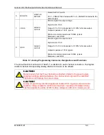
3. Set the Full Scale value from the front panel screen (Refer Figure 5-4) for
selected channel.
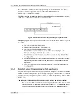
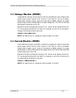
4. Connect a DC voltage source cross the VPRG_VSOUR pin and PRG_RTN pin
of the channel 1 analog programming interface connecter (refer Figure 5-10).
This will program output voltage for selected channel of the supply.
The DC voltage source is connected between Pin 1 (VPRG_VSOUR) and the return
Pin 3 (PRG_RTN) and Analog Reference source is selected as Voltage from the front
Panel. Refer to Figure 5-10.
The Full-Scale voltage value can be modified to any voltage between 5V to 10V from
front panel screen, refer to Section 3.4.9.3. Default FSC voltage value is 10V, where
10V corresponds to 100% output voltage. The corresponding voltage-programming
coefficients for output voltage are (100% rated output voltage) / FSC VDC. This
produces transfer functions for output voltage, as follows:
Vout = Vdc * (100% rated output voltage) / 10 VDC), with Vdc in volts, or
Vout = Vdc * (100% rated output voltage) / FSC VDC), with Vdc in volts.
Figure 5-10: Remote Voltage Programming Using 0-10 VDC Source
Example:
Program Full Scale Value of Voltage to 8V and program output voltage into
60% of rated output voltage using voltage source:
•
Navigate to Voltage Ref Mode menu,
•
Select Channel and set EXT Mode; refer Figure 5-8.
•
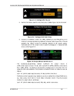
Navigate to Configure Reference Source menu,
•
Select Channel and set reference source as Resistive; refer Figure 5-3.
•
Navigate to Configure Full Scale Value menu,
•
Select Channel and set Full Scale Value for Voltage into 8V (100% of FSC); refer
•
Connect a DC voltage source across the respective channel analog
programming connector between VPRG_VSOUR and PRG_RTN terminal and
apply 4.8V; refer Figure 5-10.
•
Verify the output Voltage from the measurement screen for respective channel;
refer Figure 5-5.