


46-622 Series 3 Liquid Level Switches ASME B31.3 Construction
15
4.2.2 Check Sensing Unit
1. Reconnect power supply. Carefully actuate the switch
mechanism manually (use a non-conductive tool on elec-
trical switch mechanisms) to determine whether controlled
equipment will operate.
Caution:
With electrical power on, avoid contact with switch leads
and connections at terminal block.
2. If controlled equipment responds to manual switch actua-
tion test, trouble may be located in the level sensing por-
tion of the control, float(s), stem(s), and magnetic attrac-
tion sleeve(s).
3. Check to be certain liquid is entering float chamber.
A valve may be closed or piping plugged.
Caution:
Be certain to pull disconnect switch or otherwise ensure
that electrical circuit(s) through control is deactivated.
Close operating medium supply valve on controls
equipped with pneumatic switch mechanisms.
4. Disconnect wiring from supply side of switch mechanism(s)
and remove electrical conduit or operating medium line
connections to switch housing.
5. Perform system shutdown to relieve pressure from float
chamber of control and allow unit to cool.
6. Close shutoff valves (if equipped) to isolate control from
vessel. Drain off liquid in chamber if necessary
7. On installations without shutoff valves, relieve pressure
from vessel and drain off liquid head above control
mounting level.
NOTE: Control chamber, connections, and pipe lines need not be
removed from vessel or boiler.
8. Remove switch housing assembly by loosening enclosing
tube hex nut, which is located immediately below housing
base. Refer to
Figure 6
on 8.
9. With switch housing assembly removed, inspect attraction
sleeve(s) and inside of enclosing tube for excessive corrosion
or solids buildup, which could restrict movement, prevent-
ing sleeve(s) from reaching field of switch magnet(s).
10. If differential has been changed in the field by reposition-
ing the lower jam nuts on the float stem, check tightness
and position of the jam nuts.
11. Check float to be certain it is buoyant in the liquid (float
chamber or vessel must have adequate liquid level). If float
is determined to be filled with liquid, or it is collapsed, it
must be replaced immediately.
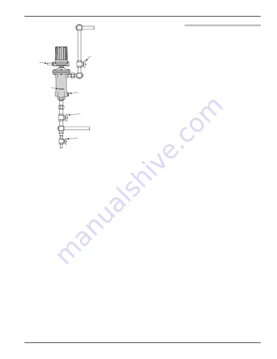
Optional blow-down
or drain valve
Shutoff valve
(if used)
Conduit
outlet
Switch
actuating
level reference
mark
Optional liquid leg
connection to vessel
Shutoff valve
(if used)
Figure 11


