American Standard ZZSENSAL0400AA Скачать руководство пользователя страница 3

Pub. No.  18-HD31D1-1

3

Installer’s Guide

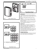
  Fig. 5.                       Wiring Multiple  Sensors.

MULTIPLE A 402

SENSORS MUST BE ARRANGED IN THIS
CONFIGURATION TO OPERATE CORRECTLY.

RS2

SENSOR SENSOR

SENSOR SENSOR

RS2

SENSOR SENSOR

SENSOR SENSOR

SENSOR

SENSOR

SENSOR SENSOR SENSOR

RS1

RS1

1

1

1

  Fig. 6.

Room Temperature Reading on

*CONT402 Comfort Control.

OPERATION

Once installed and the Comfort Control Installer Setup is
complete, the remote inside temperature is displayed on the
Comfort Control Home Screen as the Room Temperature.  See
Fig. 6.
The Remote Indoor Temperature Sensor converts room
temperature to a resistance that the Comfort Control can
interpret.
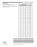
The Sensor has a negative temperature coefficient (NTC),
which means that resistance decreases as the temperature
increases. See Table 1.
The Sensor can be used to provide one remote input (see Fig.
3) or as a temperature averaging network with multiple
Sensors connected, as shown in Fig. 5.

CHECKOUT

For best results, leave the Remote Indoor Temperature
Sensor at a stable room ambient for a minimum of twenty
minutes before taking a resistance measurement.
With an accurate thermometer (±1°F [0.5°C]) measure the
temperature at the sensor location, allowing time for the
thermometer to stabilize before reading.
To verify sensor resistance, remove one wire from one of the
Sensor wiring terminals. Use an ohmmeter to measure the
resistance across the sensor. Then verify the sensor accuracy
with the temperature/resistance in Table 1 on page 4.
Reinstall the removed wire.

TROUBLESHOOTING

If the remote indoor temperature sensor fails, control reverts
to the on-board temperature sensor.  Therefore, the comfort
control must be installed in the conditioned space.

  Fig. 4.                   Sensor subbase and cover

Содержание ZZSENSAL0400AA

Страница 1: ...led pipes or ducts ii Drafts from fireplaces or other heat sources iii Convection or radiant heat from the sun or electrical equipment b Cold areas caused by i Concealed pipes or ducts ii Drafts from windows and doors iii Unheated areas on the other side of the wall location c Dead air areas i Behind doors furniture and curtains ii In corners and alcoves 4 Remove remote indoor sensor cover by gras...

Страница 2: ... Do not route temperature sensor wiring with building power wiring next to control contactors or near light dimming circuits electric motors or welding equipment Avoid poor wiring connections Avoid intermittent or missing building earth ground CAUTION Disconnect power supply before connecting wiring Failure to do so may cause equipment damage Wiring must comply with applicable codes ordinances and...

Страница 3: ...es See Table 1 The Sensor can be used to provide one remote input see Fig 3 or as a temperature averaging network with multiple Sensors connected as shown in Fig 5 CHECKOUT For best results leave the Remote Indoor Temperature Sensor at a stable room ambient for a minimum of twenty minutes before taking a resistance measurement With an accurate thermometer 1 F 0 5 C measure the temperature at the s...

Страница 4: ...7 0K 58 14 4 16 1K 60 15 6 15 3K 62 16 7 14 5K 64 17 8 13 8K 66 18 9 13 1K 68 20 0 12 5K 70 21 1 11 9K 72 22 2 11 3K 74 23 3 10 8K 76 24 4 10 2K 78 25 6 9 8K 80 26 7 9 3K 82 27 8 8 9K 84 28 9 8 5K 86 30 0 8 1K 88 31 1 7 7K 90 32 2 7 3K 92 33 3 7 0K 94 34 4 6 7K 96 35 6 6 4K 98 36 7 6 1K 100 37 8 5 8K Table 1 Sensor Resistance at Room Temperature Installer s Guide CALIBRATION The Remote Indoor Temp...

Отзывы: