American Standard L8V1A040U3VSAA Скачать руководство пользователя страница 19

18-CE15D1-1C-EN

19

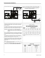
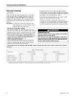
EXTERNAL MASONRY CHIMNEY

Venting of fan assisted appliances into external chimneys (one or more walls
exposed to outdoor temperatures), requires the chimney be lined with type "B",
double wall vent or suitable flexible chimney liner material. This applies in all
combinations of common venting as well as for fan assisted appliances vented
alone.
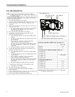
The following installation practices are recommended to minimize corrosion caused
by condensation of flue products in the furnace and flue gas system.

1.

Avoid an excessive number of bends.

2.

Horizontal runs should pitch upward at least 1/4" per foot.

3.

Horizontal runs should be as short as possible.

4.

All vent pipe or connectors should be securely supported and must be inserted
into, but not beyond the inside wall at the chimney vent.

5.

When vent connections must pass through walls or partitions of combustible
material, a thimble must be used and installed according to local codes.

6.

Vent pipe through the roof should be extended to a height determined by
National Fuel Gas Code or local codes. It should be capped properly to prevent
rain water from entering the vent. Roof exit should be waterproofed.

7.

Use type "B" double wall vent when vent pipe is routed through cool spaces
(below 60° F.).

8.

Where long periods of airflow are desired for comfort, use long fan cycles
instead of continuous airflow.

9.

Apply other good venting practices as stated in the venting section of the
National Fuel Gas Code ANSI Z223.1 "latest edition".

10.

Vent connectors serving appliance vented by natural draft or non-
positive pressure shall not be connected into any portion of a
mechanized draft system operating under positive pressure.

11. Horizontal pipe runs must be supported by hangers, straps or other suitable

material in intervals at a minimum of every 3 feet of pipe.

12. A furnace shall not be connected to a chimney or flue serving a separate

appliance designed to burn solid fuel.

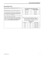
13. The flow area of the largest section of vertical vent or chimney shall not exceed

7 times the smallest listed appliance categorized vent area, flue collar area, or
draft hood outlet area unless designed in accordance with approved
engineering methods.

Maximum Vent or Tile Lined Chimney Flow Area = [

π

π

(D*)

2

]/4 X 7

* Drafthood outlet diameter, flue collar diameter, or listed appliance categorized
vent diameter.

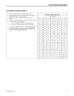
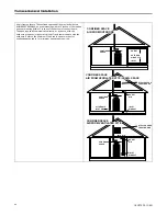
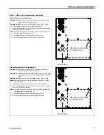
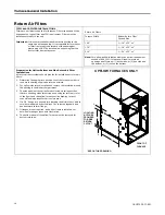
Gas Vent Termination

Roof Pitch

Minimum Height

Flat to 6/12
Over 6/12 to 7/12
Over 7/12 to 8/12
Over 8/12 to 9/12
Over 9/12 to 10/12
Over 10/12 to 11/12
Over 11/12 to 12/12
Over 12/12 to 14/12
Over 14/12 to 16/12
Over 16/12 to 18/12
Over 18/12 to 20/12
Over 20/12 to 21/12

1.0 Feet

(a)

1.25 Feet
1.5 Feet
2.0 Feet
2.5 Feet
3.25 Feet
4.0 Feet
5.0 Feet
6.0 Feet
7.0 Feet
7.5 Feet
8.0 Feet

(a)

This requirement covers most installations

Vertical Wall

Lowest Discharge
Opening

8 ft.

Listed
Cap

Minimum
Height

Roof Pitch is X/12

The vent termination should not be
less than 8 ft. from a vertical wall.

(a)

This requirement covers most installations

F

Fu

urrn

na

acce

e G

Ge

en

ne

erra

all IIn

nsstta

alllla

attiio

on

n

Содержание L8V1A040U3VSAA

Страница 1: ...e and on the tags stickers and labels that are attached to the equipment March 2022 1 18 8 C CE E1 15 5D D1 1 1 1C C E EN N Upflow Horizontal Left Right Gas Fired Single Stage Induced Draft Furnace wi...

Страница 2: ...ct ti io on ns s A A f fi ir re e o or r e ex xp pl lo os si io on n m ma ay y r re es su ul lt t c ca au us si in ng g p pr ro op pe er rt ty y d da am ma ag ge e p pe er rs so on na al l i in nj ju...

Страница 3: ...C CT TR RI IC CA AL L S SH HO OC CK K H HA AZ ZA AR RD D F Fa ai il lu ur re e t to o f fo ol ll lo ow w t th hi is s W Wa ar rn ni in ng g c co ou ul ld d r re es su ul lt t i in n p pr ro op pe er r...

Страница 4: ...y y i in ns sp pe ec ct te ed d t to o i in ns su ur re e n no o c cr ra ac ck ks s o or r o ot th he er r p po ot te en nt ti ia al l a ar re ea as s f fo or r f fl lu ue e g ga as s l le ea ak ks s...

Страница 5: ...c co ou ul ld d r re es su ul lt t i in n p pe er rs so on na al l i in nj ju ur ry y D Do o N NO OT T t to ou uc ch h i ig gn ni it te er r I It t i is s e ex xt tr re em me el ly y h ho ot t C CA AU...

Страница 6: ...te ed d t to o t th he e v ve en nt ti in ng g s sy ys st te em m T Tu ur rn n o on n a an ny y e ex xh ha au us st t f fa an ns s s su uc ch h a as s r ra an ng ge e h ho oo od ds s s so o t th he e...

Страница 7: ...e Adjustment 16 High Altitude Derate 17 General Venting 18 Air for Combustion and Ventilation 20 Duct Connections 23 Return Air Filters 30 Electrical Connections 32 Field Wiring 32 General Start up an...

Страница 8: ...ng and air conditioning equipment can be hazardous and requires specific knowledge and training Improperly installed adjusted or altered equipment by an unqualified person could result in death or ser...

Страница 9: ...inal air conditioning CFM delivered when pressurized to 5 water column with all inlets outlets and drains sealed General Guidelines The manufacturer assumes no responsibility for equipment installed i...

Страница 10: ...SIDE SIDE FRONT FURNACE 3 Is there sufficient space for servicing the Furnace and other equipment A minimum of 24 inches front accessibility to the Furnace must be provided Any access door or panel m...

Страница 11: ...18 CE15D1 1C EN 11 Outline Drawing Table 2 14 5 17 5 21 and 24 5 Width Cabinets...

Страница 12: ...des and service access to the front of the furnace See the Locations and Clearances p 10 Minimum 1 5 air clearance is required under the furnace when in horizontal Support material if underneath the f...

Страница 13: ...Manual Shut off Main Manual Shut off Valve Ground Union Joint Drip Leg 1 8 NPT Test Fitting Note For ease of installation optional accessory part PIP02095 is recommended for gas piping entering the ri...

Страница 14: ...s supply to the unit using a ground joint union and a manual shut off valve National codes require a condensation drip leg to be installed ahead of the gas valve The furnace and its individual shut of...

Страница 15: ...utility company and compare to the nameplate rating This must not exceed the nameplate rating Gas Flow in Cubic Feet Per Hour 2 Cubic Foot Dial Sec Flow Sec Flow Sec Flow Sec Flow 10 732 31 236 52 141...

Страница 16: ...the light off manifold pressure remove the low LO adjustment regulator cover screw a To increase outlet pressure turn the regulator adjust screw clockwise b To decrease outlet pressure turn the regula...

Страница 17: ...PLACEMENT ORIFICES DRILL SIZE J TUBE PART NUMBER A040 3 2 mm TUB15871 A060 23 TUB15353 B080 15 TUB15443 C100 11 TUB15780 Turn the main Gas Valve toggle switch within the unit to the OFF position Turn...

Страница 18: ...SONRY CHIMNEYS Venting of fan assisted appliances into a lined internal masonry chimney is allowed only if it is common vented with at least one natural draft appliance OR if the chimney is lined with...

Страница 19: ...on of the National Fuel Gas Code ANSI Z223 1 latest edition 10 Vent connectors serving appliance vented by natural draft or non positive pressure shall not be connected into any portion of a mechanize...

Страница 20: ...eplaces must be considered to avoid unsatisfactory Furnace operation Furnace location may be in an unconfined space or a confined space Unconfined space are installations with 50 cu ft or more per 100...

Страница 21: ...l Note Extended warranties are not available in some instances Extended warranty does not cover repairs to equipment installed in establishments with corrosive atmospheres including but not limited to...

Страница 22: ...e with the outdoors Refer to the Minimum Free Area in square inches for confined spaces table for minimum open areas required CONFINED SPACE AIR FROM OUTDOORS CONFINED SPACE OUTLET OUTDOOR AIR DUCTS I...

Страница 23: ...outlet duct be provided with a removable access panel The opening shall be accessible when the furnace is installed and shall be of such a size that the heat exchanger can be viewed for possible open...

Страница 24: ...uide holes are located on the coil 4 Seal per local codes and requirements Furnace in Horizontal Left with Coil 1 Bend furnace flanges up 2 Support the furnace and coil independently 3 Screw through t...

Страница 25: ...port the furnace and coil independently 3 Match the coil up flush to the back of the furnace 4 Seal per local codes and requirements Note Flat or dedicated horizontal coils may require flanges to be b...

Страница 26: ...rain pan must be installed in all applications over a finished ceiling to prevent property damage Minimum return air is 55oF and maximum is 80oF Upflow Furnace with Bottom Return in Closet with Remote...

Страница 27: ...rom a remote location 3 Install filter at a remote location 4 Seal per local codes and requirements Upflow Furnace with Bottom Return Mounted on a Ducted Pedestal with Filter Box 1 Remove the bottom p...

Страница 28: ...ote The furnace bottom pedestal must be a minimum of 6 in height 3 Match the filter cabinet flush to the back and bottom sides of the furnace cabinet and secure in place with screws 4 Mark the two are...

Страница 29: ...turns Important One of the sides must have a transition to allow the thermostat wiring to exit the cabinet Important If a transition is not a viable option a hole will need to be drilled in the side o...

Страница 30: ...allations All return air duct systems should provide for installation of return air filters 1 Determine the appropriate position to set the furnace in order to connect to existing supply and return du...

Страница 31: ...ts to the furnace If only the front of the furnace is accessible it is recommended that both supply and return air plenums are removable 3 When replacing a furnace old duct work should be cleaned out...

Страница 32: ...the 120V power supply must be connected to the black power lead as indicated on the wiring diagram Refer to the SERVICE FACTS literature and unit wiring diagram attached to furnace Field Wiring O Y2...

Страница 33: ...oor Unit NOTES 1 Cut the BK jumper at the indoor unit After cutting the jumper power must be off or cycled on off on for the IFC to work properly 2 Requires an 850 control with software version 3 0 or...

Страница 34: ...off For complete shutdown Turn the toggle or control switch located on the main gas valve inside the unit to the OFF position and the external main gas shutoff valve to the OFF position Disconnect th...

Страница 35: ...rnace has been rotated if needed Table 5 Venting Options for Upflow Applications Refer to the illustrations below to find the approved venting options for upflow furnace Important The exhaust must be...

Страница 36: ...ipe to the inducer outlet Pressure Switch locations L8V1 Pressure Transducer and Pressure Switch are connected to the hot header Upflow orientation with top venting Important The combustion air duct M...

Страница 37: ...e installed on C100 upflow applications Failure to install will result in nuisance burner box limit trips Note Future C100 furnaces with the Burner Box limit on the bottom DO NOT require the Combustio...

Страница 38: ...ucer when installing the furnace in upflow position with the combustion air vented through the top Note Self tapping screws are recommended for attaching the vent pipe to the inducer outlet Horizontal...

Страница 39: ...tem by momentarily depressing the MENU key and then depress the OPTION key to the desired se ng Then momentarily depress the MENU key again to save the change CFM per Ton selec ons range from 290 450...

Страница 40: ...M Airflow display is rounded down to the nearest 10 cfm NOTES 1 The menu status displayed is solely dependent on the input of 24VAC that is applied to the low voltage terminal strip 2 The status will...

Страница 41: ...heat speed for 10 seconds The above sequence will repeat two more mes unless the Run Test Mode is exited see above Important The Run Test Mode does not test fire the furnace or bring the outdoor unit...

Страница 42: ...3 The last 6 faults can be viewed Clearing the Last 6 Faults 1 To clear the last 6 faults press the Menu key until the Last 6 Faults L6F menu appears 2 Enter the menu by pressing the Option key 3 Hold...

Страница 43: ...Airflow Setting CFM Ton EXTERNAL STATIC PRESSURE IN W C 0 1 0 3 0 5 0 7 0 9 L8V1C100U5VSAA 450 CFM 1773 1769 1765 1760 1754 WATTS 364 430 501 576 653 420 CFM 1654 1652 1649 1646 1640 WATTS 301 364 43...

Страница 44: ...ur N No ot te e Typical flame current ranges from 0 75 3 0 a 6 Once flame sense has been established the igniter is de energized the blower on timer begins and the inducer ramps to the Pre Run speed D...

Страница 45: ...hermostat wiring 3 The indoor blower ramps to the HP heating airflow The seven segment LED for example will alternately read H HP P1 1 Heat Pump Heating Stage 1 A AR RF F Airflow 0 08 80 0 800 calcula...

Страница 46: ...46 18 CE15D1 1C EN N No ot te es s...

Страница 47: ...18 CE15D1 1C EN 47 N No ot te es s...

Страница 48: ...lications For more information please visit www trane com or www americanstandardair com The manufacturer has a policy of continuous data improvement and it reserves the right to change design and spe...

Отзывы: