17
Routine Maintenance
Bearings
Periodically check the bearings for wear or damage according to the
following schedule:
Guide rollers after 1
st
200 hrs.
Idler pulley
after 1
st
200 hrs.
Rollers
Periodically check the guide rollers and the tension roller for wear.
EN
The following items need to be periodically inspected and maintained to keep your sander in good working condition.
Sanding Chamber
Periodically blow out the sanding chamber to prevent large accumulations of debris which could interfere with the performance of the tension
roller. NOTE: The tension lever should be in the run/tight abrasive position to blow out.
Wheels
Periodically remove the debris from the truck and caster wheels. Debris can cause waves on a sanded surface.
Upper Roller
Remove the upper roller and blow dust and debris out of upper roller assembly regularly. If dust and debris get compacted in assembly, paper
tracking issues will occur.
Dust Bag
Remove the dust bag from the machine, unzip, empty and shake thoroughly to remove sanding dust from the bag. Turn the dust bag inside
out and hand wash in cold water and let air dry to prevent pore blockage and loss of dust recovery.
Drive Belt
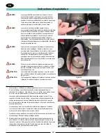
To increase belt tension, open belt guard door and release tension using quick release lever. (See figure 8) Turn the adjustment screw “OUT”
(See figure 45) one quarter turn. Restore tension using quick release lever and check adjustment. Repeat this process if necessary. To lower
tension, the adjustment screw is turned “IN”.
Handle Height Adjustment
1. Remove power.
2. Lower the control lever.
3. Depress the button on the link rod. Twist outer tube to disengage.
(See figure 42)
4. Loosen the handle lever on the front of the handle tube. (See figure 43)
5. Pull the pin on the side of the handle tube and position operator
handle as desired. (See figure 44)
Note: The handle has 4 height positions. The pull pin should fall into
one of those positions.
6. Tighten the handle lever on the front of the handle tube.
7. Raise the control lever until the link rod snaps into place.
Then twist the outer tube to lock into place.
Figure 44
Figure 45
Figure 42
Figure 43
Fan shaft
after 1
st
500 hrs.
Tension roller after 1
st
500 hrs.
Arbor shaft
after 1
st
500 hrs.
Motor shaft
after 1
st
500 hrs.
Содержание 07236A
Страница 1: ...Belt Sander Legend Operator s Manual...
Страница 2: ...2...
Страница 20: ...20...
Страница 39: ...39 Wiring Diagram...
Страница 46: ...46 Motor Assembly MOTOR ASSEMBLY 22 6 5 17 7 8 25 3 4 1 2 15 10 9 14 13 21 19 12 16 11 20 18 27 RF082100 041621...
Страница 64: ...64 Transport Dolly Assembly RF083000 022421 1 3 4 2 8 5 7 6 TRANSPORT DOLLY ASSEMBLY...
Страница 68: ...68...
Страница 70: ...70...
Страница 71: ...71...


