INSTALLATIONS
MI961F User’s Manual
17
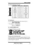
J6: 24-pin ATX Power Connector
Signal Name
Pin #
Pin #
Signal Name
3.3V
13
1
3.3V
-12V
14
2
3.3V
Ground
15
3
Ground
PS-ON
16
4
+5V
Ground
17
5
Ground
Ground
18
6
+5V
Ground
19
7
Ground
-5V
20
8
Power good
+5V
21
9
5VSB
+5V
22
10
+12V
+5V
23
11
+12V
Ground
24
12
+3.3V
J7: Power LED
The power LED indicates the status of the main power switch.
Pin #
Signal Name
1
Power LED
2
No connect
3
Ground
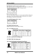
J8, J9, DDR3 DIMM Sockets
J10: System Function connector
ATX Power ON Switch: Pins 1 and 2
This 2-pin connector is an “ATX Power Supply On/Off Switch” on the
system that connects to the power switch on the case. When pressed, the
power switch will force the system to power on. When pressed again, it
will force the system to power off.
Содержание MI961F
Страница 1: ...MI961F Intel H61 Express Chipset Mini ITX Motherboard USER S MANUAL Version 1 0A...
Страница 4: ...iv MI961F User s Manual This page is intentionally left blank...
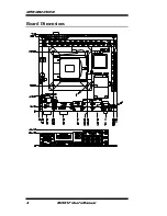
Страница 8: ...INTRODUCTION 4 MI961F User s Manual Board Dimensions...
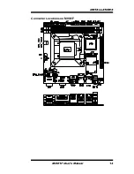
Страница 17: ...INSTALLATIONS MI961F User s Manual 13 Connector Locations on MI961F...
Страница 24: ...INSTALLATIONS 20 MI961F User s Manual This page is intentionally left blank...
Страница 64: ...APPENDIX 60 MI961F User s Manual This page is intentionally left blank...


