


Chapter 1 General Information
7
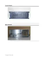
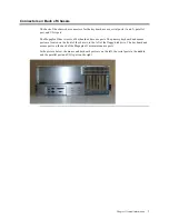
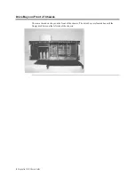
Connectors on Back of Chassis
The back of the chassis has connectors for the keyboard, mouse, serial ports (1 and 2), parallel
port, and VGA port.
The Megaplex II has two sets of keyboard and mouse ports. The primary keyboard and mouse
ports are located on the front of the chassis, to the left of the floppy disk drive. The keyboard and
mouse ports on the back of the Megaplex II are maintenance ports.
In the picture below, the mouse and keyboard ports are on the left, the serial ports in the middle,
and the parallel port and VGA port on the right.


