


10
Rev. 5
Introduction
Operating Characteristics
1.7 Operating Characteristics
The Model 430 Programmer has
been designed to perform with var-
ious power supplies to allow the
user the greatest degree of system
flexibility. The power supply and
Programmer combination are cate-
gorized by one of three forms:
sin-
gle-quadrant
,
dual-quadrant
, and
four-quadrant
. For sake of clarity,
the term
quadrant
is defined as
one of four areas of a cartesian
coordinate system where the
abscissa is current and the ordi-
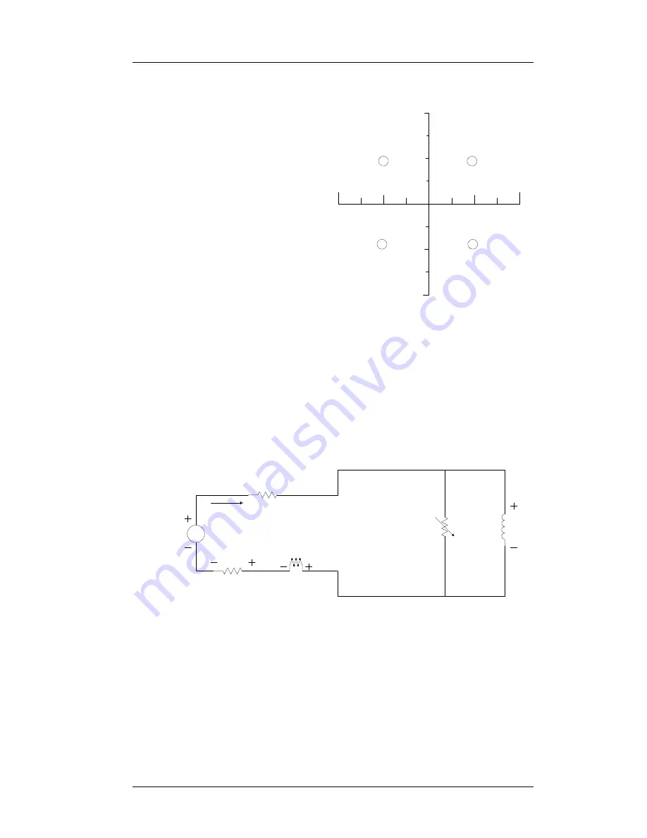
nate is voltage. Refer to Figure 1-4.
1.7.1
Dual-Quadrant Operation
In the Model 05100PS-430-601 dual-quadrant Power Supply system, an
energy absorber is added in series with the unipolar supply; this allows
stored magnetic energy to be converted to thermal energy, thereby
allowing much faster magnetic field reduction. This corresponds to
operation in quadrants 1 and 4 of Figure 1-4. The disadvantage to this
type of system is that energy is being dissipated in the energy absorbing
element whenever current is flowing. This loss is sometimes a significant
portion of the power required to operate the system.
The high-stability dual-quadrant precision current transducer-based
variation, depicted in Figure 1-6, typically increases the system stability
20
-20
200
-200
V
I
Positive Current
Flow Direction
Positive Voltage
Polarity
Positive Current
Flow Direction
Negative Voltage
Polarity
Negative Current
Flow Direction
Positive Voltage
Polarity
Negative Current
Flow Direction
Negative Voltage
Polarity
1
2
4
3
Figure 1-4.
The Four Regions, or
Quadrants, of System Operation.
Magnet
Coil(s)
Persistent
Switch
(optional)
Misc. Line Losses
Model 420
Shunt
Energy
Absorber
V
Unipolar
Power Supply
Current
Figure 1-5.
Dual-Quadrant System with Resistive Shunt
430
Содержание 05100PS-430-601
Страница 2: ......
Страница 10: ...x Rev 5 List of Figures ...
Страница 12: ...xii Rev 5 List of Tables ...
Страница 18: ...xviii Rev 5 Foreword Safety Summary ...
Страница 30: ...12 Rev 5 Introduction Operating Characteristics ...
Страница 42: ...24 Rev 3 Installation Power Up Procedure ...
Страница 114: ...96 Rev 5 Operation Summary of Operational Limits ...
Страница 119: ...Rev 5 101 Remote Interface Reference SCPI Command Summary LOCK ABsorber LOCK BRIGHTness LOCK NETsetup ...
Страница 156: ...138 Rev 5 Remote Interface Reference Error Messages ...
Страница 168: ...150 Rev 5 Service Return Authorization ...
Страница 190: ...172 Rev 5 Appendix Power Supply Details Figure A 3 Model 08150PS Dimensions Top and Side Views ...
Страница 220: ...202 Rev 5 Appendix Persistent Switch Operation Flowchart Figure A 17 Persistent Switch Operation Flowchart Page 3 ...
Страница 226: ...208 Rev 5 Index ...