158
Rev. 5
Appendix
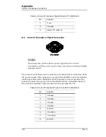
Quench I/O Connector
a suitable cable to connect pins 5 and 6 on J2 of the 13x instrument to pins
6 and 7 of the 430 Programmer, Quench I/O connector.
Caution
The separate external segmented-rampdown option described below
ignores the Voltage Limit during the rampdown process.
Note
If the number of external-rampdown ramp segments is set to zero,
the modified rampdown is not used and the standard ramp rate
table will be effective during external rampdown. The Model 430
Programmer defaults to an empty rampdown table (number of
segments equal zero).
A separate segmented-ramp-rate table is available for external rampdown.
This option is accessible only via the external interface commands. See
A.6.3
External Quench Detection Output
The external quench detection output is a set of dry contacts (pins 1 and 2
of the Quench I/O connector) which
close
when the Model 430 Programmer
internal circuitry detects a quench condition. Note that the Model 430
Programmer internal quench detection must be enabled to assure that the
Model 430 Programmer will indicate a detected quench (see
section 3.10.2.13 on page 61).
The contacts remain shorted (when a quench has been detected) until the
RESET QUENCH
SHIFT-key is used to clear the quench condition.
Содержание 05100PS-430-601
Страница 2: ......
Страница 10: ...x Rev 5 List of Figures ...
Страница 12: ...xii Rev 5 List of Tables ...
Страница 18: ...xviii Rev 5 Foreword Safety Summary ...
Страница 30: ...12 Rev 5 Introduction Operating Characteristics ...
Страница 42: ...24 Rev 3 Installation Power Up Procedure ...
Страница 114: ...96 Rev 5 Operation Summary of Operational Limits ...
Страница 119: ...Rev 5 101 Remote Interface Reference SCPI Command Summary LOCK ABsorber LOCK BRIGHTness LOCK NETsetup ...
Страница 156: ...138 Rev 5 Remote Interface Reference Error Messages ...
Страница 168: ...150 Rev 5 Service Return Authorization ...
Страница 190: ...172 Rev 5 Appendix Power Supply Details Figure A 3 Model 08150PS Dimensions Top and Side Views ...
Страница 220: ...202 Rev 5 Appendix Persistent Switch Operation Flowchart Figure A 17 Persistent Switch Operation Flowchart Page 3 ...
Страница 226: ...208 Rev 5 Index ...


