Rev. 5
151
Appendix
A.1
Magnet Station Connectors
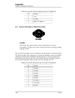
The two 25-pin D-sub female Magnet Station Connectors are identically
wired and connected pin-for-pin internally. Spare connections may be used
for custom coil taps or other signals.
Table A-1.
Magnet Station Connectors Pin Definitions
Pin
Function
Pin
Function
1
LHe Sensor I+ (Red)
14
spare
2
LHe Sensor I
−
(Black)
15
spare
3
LHe Sensor V
−
(Yellow)
16
spare
4
LHe Sensor V+ (Blue)
17
spare
5
Temperature Sensor I+ (Red)
18
spare
6
Temperature Sensor I
−
(Black)
19
spare
7
Temperature Sensor V
−
(Yellow)
20
spare
8
Temperature Sensor V+ (Blue)
21
spare
9
Persistent Switch Heater I+ (Red)
22
spare
10
Persistent Switch Heater I
−
(Black)
23
spare
11
Magnet Voltage Tap V+ (Yellow)
24
spare
12
Magnet Voltage Tap V
−
(Blue)
25
spare
13
spare
Содержание 05100PS-430-601
Страница 2: ......
Страница 10: ...x Rev 5 List of Figures ...
Страница 12: ...xii Rev 5 List of Tables ...
Страница 18: ...xviii Rev 5 Foreword Safety Summary ...
Страница 30: ...12 Rev 5 Introduction Operating Characteristics ...
Страница 42: ...24 Rev 3 Installation Power Up Procedure ...
Страница 114: ...96 Rev 5 Operation Summary of Operational Limits ...
Страница 119: ...Rev 5 101 Remote Interface Reference SCPI Command Summary LOCK ABsorber LOCK BRIGHTness LOCK NETsetup ...
Страница 156: ...138 Rev 5 Remote Interface Reference Error Messages ...
Страница 168: ...150 Rev 5 Service Return Authorization ...
Страница 190: ...172 Rev 5 Appendix Power Supply Details Figure A 3 Model 08150PS Dimensions Top and Side Views ...
Страница 220: ...202 Rev 5 Appendix Persistent Switch Operation Flowchart Figure A 17 Persistent Switch Operation Flowchart Page 3 ...
Страница 226: ...208 Rev 5 Index ...


