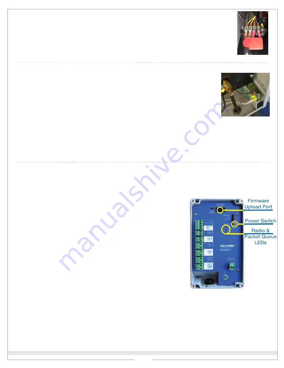
Upgrade Firmware
3
5
1
Attach
FUT
to
Unit’s Firmware Upload
port. The update begins automatically.
Ground RMU and Ground Connections to Earth Ground
1
Do not
ground the RMU if unit is inside rectifier or attached to the external
rectifier case.
If RMU is attached on another pole (not inside or attached to external
rectifier case)
, ensure the RMU’s ground is connected to a
common ground
point
on the rectifier chassis.
2
Ground connection to earth ground.
a
If there is a ground rod, check connection and ensure it is connected to rectifier
chassis.
b
If there is no ground rod, install one if possible. If one cannot be installed, make a
note in records that no ground rod is installed.
2
LED lights on the
FUT
:
Status
LED light indicates when
FUT
is updating or complete.
Activity
LED light flashes during the verification and update process.
IMPORTANT:
Unit must complete packet transmission to complete the update. If
packet transmission is not successful, repeat the firmware update process.
IMPORTANT:
Do not turn off the unit during the update process.
3
When the
Completed
status light turns on and the
Activity
light turns off,
disconnect the
FUT
.
4
LED lights on the
Unit
:
The
Acquiring Signal
light flashes to indicate
Unit
is searching for satellite
signal.
The
Packet Queue
light flashes to indicate
Unit
is transmitting. The light
turns off when Bullhorn Web receives the packet.
Unit
automatically sends a packet when update is complete.
Install DC Surge Suppressor
1
Replace existing
surge suppressor on
DC
side of stack with
DC
Surge Suppressor
from kit.
NOTE:
For
JA rectifiers
—
black/red leads = DC side of stack; yellow/white leads = AC
side of stack. You will need to replace the
Surge Suppressor
for
DC
side of stack.
4
Common Ground Location
on Rectifier Chassis
DC Surge Suppressor
5
Connect to unit using the USB cable. Open
Bullhorn Tools
and complete the following:
a
Verify that firmware was updated to version
4.7
.
b
Ensure the
Alarm Measurement Interval
field is set to 240 minutes.
c
Ensure
Channel 5
is enabled and the
accumulator
is turned on.
d
Ensure
Channel 6
is enabled.
c
Ensure
all
ground connections are installed to single point on rectifier chassis, including
DC Lightning Arrestor
,
ground rod, and potentially the RMU. A 1/4" bolt can be installed on rectifier chassis that connects ground rod to
the bolt via a copper wire (externally) and all internal ground connections (internally).
IMPORTANT:
I
f unit’s firmware version is
4.7
or later, skip this step. You can check firmware version through your
Bullhorn Web
account or by connecting the unit to
Bullhorn Tools
. Be sure to
disconnect from Bullhorn Tools
before beginning the upgrade process.
© 2020 American Innovations, Ltd.
Lightning Arrester Surge Kit Installation Quick Reference Guide
For additional information or questions, please contact Technical Support at 1-800-229-3404 or [email protected]
RM4011 Port, Switch, and LED Lights
Part No. 122248-000 Rev. 1
2 of 2


