background image

34

I.  PREPARATION FOR OPERATION/START-UP

The following items 

should be

 checked before attempting to operate the dryer:

1. Read 

ALL

 "

CAUTION

," "

WARNING

," and "

DIRECTION

" labels attached to the dryer.

2. Check incoming supply voltage to be sure that it is the same as indicated on the dryer data label affixed to

the left side panel area behind the top control (access) door (refer to the 

illustration

 in 

Section VIII

 of

this manual).  In the case of 208 VAC or 230/240 VAC 

THE SUPPLY VOLTAGE 

MUST MATCH

THE ELECTRIC SERVICE EXACTLY.

3. GAS MODELS - check to assure that the dryer is connected to the type of heat/gas indicated on the dryer

data label.

4. GAS MODELS - the sail switch damper assembly was installed and pre-adjusted at the factory to prior

shipping.  However, each sail switch adjustment 

must be

 checked to assure that this important safety

control is functioning.

5. Check to be sure that the drive belts between the idler pulley and the motor pulley have been reconnected.

NOTE

: The drive belts were disconnected at the factory prior to dryer shipment.

6. GAS MODELS - be sure that 

ALL

 gas shutoff valves are in the open position.

7. Be sure 

ALL

 back panels (guards) and electric box covers have been replaced.

8. Check 

ALL

 service doors to assure that they are closed and secured in place.

9. Be sure the lint drawer is securely in place.

NOTE: LINT DRAWER 

MUST BE

 ALL THE WAY IN PLACE TO ACTIVATE THE

SAFETY SWITCH OTHERWISE THE DRYER WILL NOT START.

10. Rotate the basket (tumbler/drum) by hand to be sure it moves freely.

11. Check bolts, nuts, screws, terminals, and fittings for security.

12. GAS MODELS and STEAM MODELS - check to insure air supply 80 PSI (5.51 bars) is connected to the

dryer.

13. STEAM MODELS - check to insure 

ALL

 steam shutoff valves are open.

14. STEAM MODELS - check steam damper operation.

15. Check basket (tumbler) bearing setscrews to insure they are 

ALL

 tight.

Содержание ID-170

Страница 1: ...f you cannot reach your gas supplier call the fire department Installation and service must be performed by a qualified installer service agency or the gas supplier AVERTISSEMENT Assurez vous de bien suivre les instructions données dans cette notice pour réduire au minimum le risque d incendie ou d explosion ou pour éviter tout dommage matériel toute blessure ou la mort Ne pas entreposer ni utilis...

Страница 2: ...his manual as complete as possible and hope you will find it useful ADC reserves the right to make changes from time to time without notice or obligation in prices specifications colors and material and to change or discontinue models The illustrations included in this manual may not depict your particular dryer exactly Important For your convenience log the following information DATE OF PURCHASE_...

Страница 3: ...YER S IN OPERATION DRYER S SHOULD NEVER BE LEFT UNATTENDED WHILE IN OPERATION CAUTION FOR YOUR SAFETY DO NOT DRY MOP HEADS IN THE DRYER DO NOT USE DRYER IN THE PRESENCE OF DRY CLEANING FUMES WARNING UNDER NO CIRCUMSTANCES should the dryer door switch the lint drawer switch or the heat safety circuit devices ever be disabled Caution Label all wires prior to disconnection when servicing controls Wir...

Страница 4: ...ayed on the equipment and or specified in the installation manual included with the dryer WARNING DRYER MUST NEVER BE OPERATED WITHOUT THE LINT FILTER SCREEN IN PLACE EVEN IF AN EXTERNAL LINT COLLECTION SYSTEM IS USED Dryers must not beinstalled or stored in an area where itwill be exposed to water or weather The wiring diagram for the dryer is located in the front electrical control box area ...

Страница 5: ...g Setting Up 11 C Dryer Enclosure Requirements 14 D Fresh Air Supply Requirements 15 E Exhaust Requirements 16 F Electrical Information 22 G Gas Information 26 H Steam Information 30 I Preparation For Operation Start Up 34 J Preoperational Tests 35 K Compressed Air Requirements 38 L Shut Down Instructions 39 SECTION IV SERVICE PARTS INFORMATION 40 A Service 40 B Parts 40 SECTION V WARRANTY INFORMA...

Страница 6: ...ation 45 SECTION VII REVERSING TIMER SPIN DWELL ADJUSTMENTS 46 SECTION VIII DATA LABEL INFORMATION 47 A Data Label 47 SECTION IX PROCEDURE FOR FUNCTIONAL CHECK OF REPLACEMENT COMPONENTS 49 SECTION X BURNER AND BASKET TUMBLER LINT CHAMBER MANUAL RESET HI LIMIT INSTRUCTIONS 50 ...

Страница 7: ...ccepted but the number received and the number refused must be noted on the receipt 4 If you determine that the dryer was damaged after the trucker has left your location you should call the delivering carrier s freight terminal immediately and file a claim The freight company considers this concealed damage This type of freight claim is very difficult to get paid and becomes extremely difficult w...

Страница 8: ...ely call your gas supplier from a neighbor s phone Follow the gas supplier s instructions f If you cannot reach your gas supplier call the fire department 4 Installation and service must be performed by a qualified installer service agency or gas supplier 5 Dryer s must be exhausted to the outdoors 6 Although ADC produces a very versatile dryer there are some articles that due to fabric compositio...

Страница 9: ... dry cleaning solvents or fumes 11 Remove articles from the dryer as soon as the drying cycle has been completed WARNING Articles left in the dryer after the drying and cooling cycles have been completed can create a fire hazard 12 DO NOT operate steam dryers with more than 125 PSI 8 61 bars steam pressure Excessive steam pressure can damage the steam coil and or harm personnel 13 Replace leaking ...

Страница 10: ...TAINER 3 7 DRYERS PER 45 48 TRUCK 8 8 VOLTAGE AVAILABLE 208 460v 3ø 3 4w 50 60Hz APPROX WEIGHT UNCRATED 1 900 lbs 861 8 kg APPROX WEIGHT CRATED 2 066 lbs 937 14 kg HEAT INPUT 550 000 btu hr 138 600 kcal hr AIRFLOW 3 700 cfm 104 8 cmm INLET PIPE SIZE 1 1 4 F P T COMPRESSED AIR VOLUME 2 5 cfh 80 PSI 0 07 cmh 5 51 bars COMPRESSED AIR CONNECTION 1 8 N P T VOLTAGE AVAILABLE 208 460v 3ø 3 4w 50 60Hz APP...

Страница 11: ...7 NOTE ADC reserves the right to make changes in specifications at any time without notice or obligation Specifications IDG 170 Gas IDS 170 Steam ...

Страница 12: ...pad Panel Assembly controls 2 Control top access Door Assembly 3 Main Door Assembly 4 Lint Drawer 5 Lint Door 6 Wire Diagram located behind control door 7 Data Label and Installation Label 8 Top Console module Assembly B COMPONENT IDENTIFICATION 1 Dryer Front View ...

Страница 13: ...9 Illus No Description 1 Drive basket tumbler Motor 2 Drive Assembly 3 Blower Motor 4 Idler Assembly 5 Installation Label 6 Data Label 7 Heating Unit 2 Dryer Rear View ...

Страница 14: ...tion and Gas Plumbing 1 The dryer must be installed on a sound level floor capable of supporting its weight Carpeting must be removed from the floor area that the dryer is to rest on IMPORTANT The dryer must be installed on noncombustible floors only 2 The dryer must not be installed or stored in an area where it will be exposed to water and or weather 3 The dryer is for use in noncombustible loca...

Страница 15: ...very 6 months inspect the exhaust ducting and remove any lint build up B UNPACKING SETTING UP Remove protective shipping material i e plastic wrap and or optional shipping box from dryer IMPORTANT Dryer must be transported and handled in an upright position at ALLtimes The dryer can be moved to its final location while still attached to the skid or with the skid removed To unskid the dryer locate ...

Страница 16: ...e the eight 8 sets of nuts and washers B in the illustration below holding the console module to the base 3 Disconnect the white plug C in the illustration below connector located on the top of the rear electric service relay box provides power to the heat circuit 4 Disconnect air connection from the 3 way micro valve 5 Lift the console module off of the dryer base IMPORTANT The dryer must be tran...

Страница 17: ...nd exhaust ductwork a To install the transition piece align the four 4 clinch studs into the four 4 clearance holes on the dryer b Using the four 4 free spin wash nuts included with the transition piece tighten the wash nuts on the clinch studs which will secure the transition piece to the dryer c The round duct can now be connected to the dryer ...

Страница 18: ...of the dryer be positioned approximately 2 feet 24 inches from the nearest obstruction i e wall for ease of installation maintenance and service Bulkheads and partitions should be made from noncombustible materials The clearance between the bulkhead header and the dryer must bea minimum of 4 inches 10 16 cm and must not extend more than 4 inches 10 16 cm to the rear of the front A 2 inch 5 08 cm c...

Страница 19: ...eters for each steam dryer To compensate for the use of registers or louvers used over the openings this make up airmust beincreased by approximately thirty three percent 33 Make up air openingsshould not be located in an area directly near where exhaust vents exit the building It is not necessary to have a separate make up air opening for each dryer Common make up air openings are acceptable Howe...

Страница 20: ...e last dryer to the outside exhaust outlet must not exceed 20 feet 6 09 meters The shape of the ductwork is not so critical so long as the minimum cross sectional area is provided It is suggested that the use of 90º turns be avoided use 30º and or 45º bends angles instead The radius of the elbowsshould preferably be 1 1 2 times the diameter of the duct Excluding basket tumbler dryer elbow connecti...

Страница 21: ...suggested to provide a separate exhaust duct for each dryer The exhaust ductshould be laid out in such a way that the ductwork travels as directly as possible to the outdoors with as few turns as possible It is suggested that the use of 90 turns in the ducting be avoided use 30 and or 45 angles instead The shape of the exhaust ductwork is not critical so long as the minimum cross section area is p...

Страница 22: ...ure and lint from escaping into the building Inspection doors should be installed at strategic points in the exhaust ductwork for periodic inspection and cleaning of lint from the ductwork It is suggested that the ductwork from each dryer not exceed 20 feet 6 09 meters with no more than two 2 elbows excluding dryer connections If the ductwork exceeds 20 feet 6 09 meters or has numerous elbows the ...

Страница 23: ...st be installed at each dryer duct IMPORTANT No more than three 3 dryers should be connected to one 1 main common duct The main duct may be any shape or cross sectional area so long as the minimum cross section area is provided The illustrations on page 21 show the minimum cross section area for multiple dryer round or square venting These figures must be increased 10 square inches 64 51 square ce...

Страница 24: ...ing of lint from the ductwork NOTE When the exhaust ductwork passes through a wall ceiling or roof made of combustible materials the opening must be 2 inches 5 08 cm larger than the duct all the way around The duct must be centered within this duct a Outside Ductwork Protection 1 To protect the outside end of the horizontal ductwork from the weather a 90 elbow bent downward should be installed whe...

Страница 25: ...21 ...

Страница 26: ...ATEST EDITION IMPORTANT Failure to comply with these codes or ordinances and or the requirements stipulated in this manual can result in personal injury or component failure NOTE Component failure due to improper installation will VOID THE WARRANTY Each dryer should be connected to an independently protected branch circuit The dryermust be connected with copper wire only DO NOT use aluminum wire w...

Страница 27: ...C and 230 240 VAC ARE NOT THE SAME When ordering specify exact voltage NOTES A When fuses are used they must be dual element time delay current limiting class RK1 or RK5 ONLY Calculate determine correct fuse value by applying either local and or National Electrical Codes to lised appliance amp draw data B Circuit breakers are thermal magnetic industrial motor curve type ONLY For others calculate v...

Страница 28: ... service breaker In ALL cases a strain relief must be used where the wire s enter the dryer electrical service relay box NOTE A CIRCUIT SERVICING EACH DRYER MUST BE PROVIDED 3 Electrical Connections NOTE A wire diagram is included with each dryer and is affixed to the back side of the top control access door The only electrical input connections to the dryer are the 3 phase 3ø power leads L1 L2 an...

Страница 29: ...hand corner of the dryer For added personal safety when possible it is suggested that a separate ground wire sized per local codes be connected from the ground connection of the dryer to a grounded cold water pipe DO NOT ground to a gas pipe or hot water pipe The grounded cold water pipe must have metal to metal connection ALL the way to the electrical ground If there are any nonmetallic interrupt...

Страница 30: ...ill VOID THE WARRANTY WARNING FIRE OR EXPLOSION COULD RESULT 1 Gas Supply The gas dryer installation must meet the American National Standard National Fuel Gas Code ANSI Z223 1 LATEST EDITION or in Canada the Canadian Installation Codes CAN CGA B149 1 M91 Natural Gas or CAN CGA B149 2 M91 L P Gas or LATEST EDITION as well as local codes and ordinances and must be done by a qualified professional N...

Страница 31: ...nches 26 1 mb water column There is no regulator or regulation provided in an L P dryer The water column pressure must be regulated at the source L P tank or an external regulator must be added to each dryer 2 Technical Data a Gas Specifications TYPE OF GAS NATURAL LIQUID PROPANE Manifold Pressure 3 5 inches W C 8 7 mb 10 5 inches W C 26 1 mb In Line Pressure 6 0 12 0 inches W C 14 92 29 9 mb 11 0...

Страница 32: ...system Consistent gas pressure is essential at ALL gas connections It is recommended that a 1 1 2 3 18 cm pipe gas loop be installed in the supply line servicing a bank of dryers An in line pressure regulator must be installed in the gas supply line header if the natural gas pressure exceeds 12 0 inches 29 9 mb of water column W C pressure NOTE A consistent water column test pressure of 3 5 inches...

Страница 33: ... during any pressure testing of that system at test pressures in excess of 1 2 psig 3 5 kPa NOTE The dryer must be isolated from the gas supply piping system by closing its individual manual shutoff valve during any pressure test of the gas supply system at test pressures equal to or less than 1 2 psig 3 5 kPa ...

Страница 34: ... Steam Requirements High Pressure Inlet 1 1 2 supply line connection qty one 1 at top manifold Return 1 1 2 return line connection qty one 1 at bottom manifold 3 Installation Instructions To insure an adequate supply of steam is provided be sure that the steam lines and steam return lines are sized and laid out as stipulated in this manual Inadequate steam lines and steam return lines or improper ...

Страница 35: ...inverted bucket steam trap and check valve at least 12 inches 30 48 cm below the steam coil as close to the coil as possible 1 An inverted bucket steam trap with a capacity of 1 400 lbs 635 02 kg of condensate per hour 125 PSI 8 61 bars is required for each dryer f A 3 4 19 05 mm vacuum breaker should be installed This will save energy and provide for the safety of the operator and maintenance per...

Страница 36: ...ressure is achieved 5 Steam Damper System Operation The IDS 170 steam damper as shown in the top illustrationon page 33 allows the coil to stay constantly charged eliminating repeated expansion and contraction When the damper is opened the air immediately passes through the already hot coil providing instant heat to start the drying process When the damper is closed ambient air is drawn directly i...

Страница 37: ...nd adjusted prior to shipping at 80 PSI 5 51 bars steam damper operation must be checked before the dryer is put into operation Refer to theillustration above for correct steam damper operation If steam damper adjustment is necessary locate the flow control valve and make the necessary adjustments as noted below ...

Страница 38: ...nt safety control is functioning 5 Check to be sure that the drive belts between the idler pulley and the motor pulley have been reconnected NOTE The drive belts were disconnected at the factory prior to dryer shipment 6 GAS MODELS be sure that ALL gas shutoff valves are in the open position 7 Be sure ALL back panels guards and electric box covers have been replaced 8 Check ALL service doors to as...

Страница 39: ...he back of the dryer must turn in the counterclockwise CCW direction otherwise the dryer efficiency will be drastically reduced and premature component failure can result 5 Heat Circuit Operational Test a Gas Models 1 When the dryer is first started during initial start up the burner has a tendency not to ignite on the first attempt This is because the gas supply piping is filled with air so it ma...

Страница 40: ...e activated on If the heat burner does activate shut the dryer off and make the necessary adjustments 7 A reversing basket tumbler dryer should never be operated with less than a 100 lbs 45 35 kg load dry weight The size of the load will affect the coast down and dwell stop times The basket tumbler must come to a complete stop before starting in the opposite direction a Microprocessor Controller C...

Страница 41: ... Each microprocessor controller computer has be preprogrammed by the factory with the most commonly used parameter program selections If computer changes are required refer to the computer programming manual which was shipped with the dryer b Dual Timer check 1 Heating Timer 2 Cool Down Timer 3 Temperature Selection Switch ...

Страница 42: ...ements a Microprocessor controller computer dryers COMPRESSED AIR SUPPLY AIR PRESSURE Normal 80 PSI 5 51 bars Minimum Supply 70 PSI 4 82 bars Maximum Supply 90 PSI 6 21 bars Shaded areas are stated in metric equivalents 2 Air Regulation a No air regulation or air filtration is provided with the dryer External regulation filtration of 80 PSI 5 51 bars must be provided It is suggested that a regulat...

Страница 43: ...ct switch or the circuit breaker 2 Discontinue the heat supply a GAS MODELS discontinue the gas supply 1 SHUT OFF external gas supply shutoff valve 2 SHUT OFF internal gas supply shutoff valve located in the gas valve burner area b STEAM MODELS discontinue the steam supply 1 SHUT OFF external location furnished shutoff valve 2 SHUT OFF internal steam valves in the supply lines and the return lines...

Страница 44: ...rial numberso that your inquiry is handled in an expeditious manner B PARTS 1 Replacement parts should be purchased from the reseller from whom theADC equipment was purchased If the reseller cannot be contacted or is unknown contact the ADC Parts Department for a reseller in your area Parts may also be purchased directly from the factory by calling the ADC Parts Department at 508 678 9000 or you m...

Страница 45: ...rom whom you purchased the equipment and request a dryer warranty form If the reseller cannot be contacted or is unknown warranty information can be obtained from the factory by contacting theADC Warranty Department at 508 678 9000 NOTE Whenever contacting the ADC factory for warranty information be sure to have the dryer s model numberand serial numberavailable so that your inquiry can be handled...

Страница 46: ...ansit Damage claims are the responsibility of the shipper IMPORTANT No replacements credits or refunds will be issued for merchandise damaged in transit 5 ALL returns should be shipped to the ADC factory in such a manner that they are insured and a proof of delivery can be obtained by the sender 6 Shipping charges are not the responsibility of ADC ALL returns should be prepaid to the factory Any C...

Страница 47: ...AND FREE FROM COMBUSTIBLE MATERIALS GASOLINE AND OTHER FLAMMABLE VAPORS AND LIQUIDS NOTE REMOVE POWER FROM THE DRYER BEFORE PERFORMINGANY MAINTENANCE IN THE DRYER cleaning the lint drawers and both steam coil lint screens are the only exceptions NOTE Suggested time intervals shown are for average usage which is considered six 6 to eight 8 operational running hours per day IMPORTANT Dryer produces ...

Страница 48: ...gas valve burner area with a dusting brush or vacuum cleaner attachment NOTE To prevent damage avoid cleaning and or touching the Hot Surface Ignitor HSI Remove lint accumulation from inside 6 MONTHS Inspect and remove lint accumulation in customer furnished exhaust ductwork system and from dryers internal exhaust ducting NOTE THE ACCUMULATION OF LINT IN THE EXHAUST DUCTWORK CAN CREATE A POTENTIAL...

Страница 49: ...ves Complete operational check ofALL safety devices i e door switches lint drawer switch sail switch burner and hi limit thermostats ID 170 ONLY Squirrel cage type fan impellor on the blower motor must be inspected and cleaned every six 6 months C LUBRICATION The motor bearings the idler bearings and the basket tumbler bearings are permanently lubricated NO LUBRICATION IS NECESSARY 90 DAYS Re grea...

Страница 50: ...e dryer Both the dwell stop time and the basket tumbler spin time are adjustable by mode selection switches located on the electronic timer as noted in the illustration below TIMING LEGEND SPIN TIME Adjustment Position Number 1 2 3 4 5 Time in Seconds 30 60 90 120 150 DWELL STOP TIME Adjustment Position Number 1 2 3 4 5 Time in Seconds 5 6 3 7 6 8 9 10 2 Values shown are 1 second ...

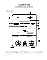
Страница 51: ... certain information is required to insure proper service parts information from ADC This information is on the data label that is affixed to the left side panel area behind the top control access door When contacting ADC please have the model numberas well as theserial number readily available ...

Страница 52: ... particular model 4 TYPE OF HEAT This describes the type of heat for your particular dryer gas either natural gas or liquid propane L P gas or steam 5 HEAT INPUT for GAS DRYERS This describes the heat input in British Thermal Units per Hour BTUH 6 ORIFICE SIZE for GAS DRYERS Gives the number drill size used 7 ELECTRIC SERVICE This describes the electric service for your particular model 8 GAS MANI...

Страница 53: ... gas valve will be energized Ignition flame should now be established e With the burner flame on remove the flame sensor wire from the S2 terminal of the HSI module The burner flame must shut off immediately f Stop the drying cycle with the flame sensor wire still removed restart the drying cycle g The HSI will turn on and after a few seconds later the gas valvewill be energized and the HSI will s...

Страница 54: ...ay will show the applicable error code described above along with an audio indication If the drum temperature is above 100º F 38º C the dryer will continue to run with no heat for 3 minutes or until the drum temperature has flattened below 100º F 38º C The clear stop button on the Phase 6 keyboard touch pad must be pressed to clear the error condition The open manual reset hi limit thermostat must...

Страница 55: ...ADC 113331 1 08 27 01 25 ...

Отзывы: