


Contents
Features 1
General Instructions 2
1. Overview 3
2. Operation Guide 5
Technical Specifications 11
1.1 Front Panel 3
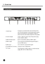
1.2 Rear Panel 4
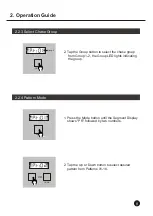
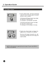
2.1 Self Test Mode 5
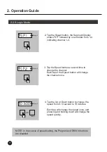
2.2 DMX Mode 7
Los Angeles, CA 90058 USA
A
VIATOR-SP8
A
VIATOR-SP8
Improvement and changes to
this manual, specifications
and design, may be made at
any time without prior notice.
ALL RIGHTS RESERVED.
American DJ
R
American DJ
R
Содержание Aviator-32
Страница 4: ...2 General Instructions...
Страница 19: ...24 004 0359 ALL RIGHTS RESERVED Rev 1 0 Jul 2000 American DJR C R American DJ Supply www americandj com...
Страница 20: ...E n g l i s h AVIATOR SP8 American DJR R Please read before use USER S MANUAL...
Страница 33: ...24 004 0384 ALL RIGHTS RESERVED Rev 1 1 Jul 2000 American DJR C R American DJ Supply www americandj com...


