I
NSTALLING
THE
SMD34K
SMD34K User Manual
ADVANCED MICRO CONTROLS INC.
86
1.6 Power Wiring (continued)
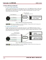
1.6.3 Auxiliary Power, Single Supply
Figure T1.4 below shows how to wire main and auxiliary power to the SMD34K units using a single supply.
When designing your own cable that uses an MS-41 connector, connections only have to be made to pin 1,
DCPower
MAIN
, pin 2, DCPower
AUX
, and pin 3, DC Common. The figure below shows how to wire a
CNGL-5M cable to the power supply.
Figure T1.4 SMD34K Auxiliary Power Wiring, Single Supply
When using the DCPower
AUX
pin, the SMD34K will report a Driver_Fault when power is
removed from the DCPower
MAIN
pin.
1.6.4 Auxiliary Power, Dual Supplies
Figure T1.5 below shows how to wire main and auxiliary power to the SMD34K units using two power
supplies. When designing your own cable that uses an MS-41 connector, connections only have to be made to
pin 1, DCPower
MAIN
, pin 2, DCPower
AUX
, and pin 3, DC Common. The figure below shows how to wire a
CNGL-5M cable to the power supplies.
Figure T1.5 SMD34K Auxiliary Power Wiring, Single Supply
When using the DCPower
AUX
pin, the SMD34K will report a Driver_Fault when power is
removed from the DCPower
MAIN
pin.
Power Control
Circuit
+24 Vdc to +80 Vdc
Power Supply
Power Control
Circuit
+24 Vdc to +80 Vdc
Main Power Supply
+24 Vdc
Aux Power Supply
Содержание SMD34K
Страница 1: ...MICRO CONTROLS INC ADVANCED U s e r M anual Manual 940 0S280 ...
Страница 6: ...TABLE OF CONTENTS SMD34K User Manual ADVANCED MICRO CONTROLS INC 6 Notes ...
Страница 50: ...CALCULATING MOVE PROFILES SMD34K User Manual ADVANCED MICRO CONTROLS INC 50 Notes ...
Страница 62: ...CONFIGURATION DATA FORMAT SMD34K User Manual ADVANCED MICRO CONTROLS INC 62 Notes ...
Страница 80: ...COMMAND DATA FORMAT SMD34K User Manual ADVANCED MICRO CONTROLS INC 80 Notes ...
Страница 100: ...LEADERS IN ADVANCED CONTROL PRODUCTS ADVANCED MICRO CONTROLS INC ...


