NETWORK DATA FORMATS
ADVANCED MICRO CONTROLS INC.
7
52
Configuration Mode
Network Output Data (Configuration Mode)
The correct format for the Network Output Data when the SD17060E is in Configuration Mode is shown
below.
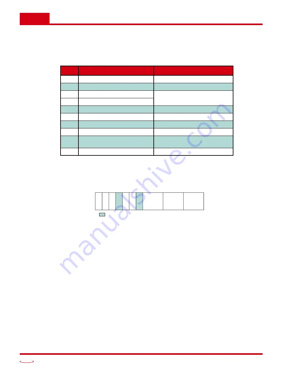
Table 7.2 Network Output Data Format: Configuration Mode
Control Word Format (Word 0)
Figure 7.1 Configuration Mode: Control Word Format
Bit 15: Mode Bit –
“1” for Configuration Mode Programming, “0” for Command Mode Programming. The
SD17060E powers up in Configuration Mode and will not switch to Command Mode until a valid
configuration is written to the drive. Power is also removed from the motor until the SD17060E has
a valid configuration written to it.
Bit 14: Anti-Resonance Enable Bit –
“0” enables the anti-resonance feature of the SD17060E. “1” dis-
ables the anti-resonance feature. The Anti-resonance feature will provide smoother operation in
most cases. If you are still experiencing resonance problems with this feature enabled, disable this
feature and test the machine again.
Bit 13: Stall Detection Enable Bit –
“0” disables motor stall detection. “1” enables motor stall detection.
Only valid when an encoder is used and attached to the motor controlled by the SD17060E.
Bit 11: Home Proximity Bit Enable Bit –
“0” when Home Proximity bit is not used when homing the
SD17060E. “1” when the Home Proximity bit is used when homing the SD17060E. Note that this
bit is not the Home Proximity Bit, but enables or disables its operation.
Bit 10: Quadrature Encoder Enable Bit –
“0” when Quadrature Encoder is not used. “1” to enable a
Quadrature Encoder. When using a Quadrature Encoder, you must program Inputs 1 and 2 to accept
quadrature signals in addition to setting this bit.
Bit 9:
Reserved –
Must equal zero.
Word
Configuration Data
Range
0
Control Word
See below
1
Config Word
See below
2
Starting Speed: Upper Word
Combined value between 1
and 999,999 steps/sec.
3
Starting Speed: Lower Word
4
Motor Steps/Turn
200 to 32,767
5
Reserved
Must be 0000h
6
Encoder Pulses/Turn
0 to 32,768
7
Idle Current Percentage
0 to 100%
8
Motor Current (X10)
10 to 60, Even numbers only.
Represents 1.0 to 6.0 A
RMS
9
Current Loop Gain
1 to 40
0
Control Word
15 14 13 12 11 10 09 08 07 06 05 04 03 02 01 00
MOD
E
AR-
E
n
0
RESERVED: Bit must equal zero.
St
a
ll-
En
HP
ro
x-E
n
Qu
ad
-E
n
Input 3
Config
Input 2
Config
Input 1
Config


