6/30
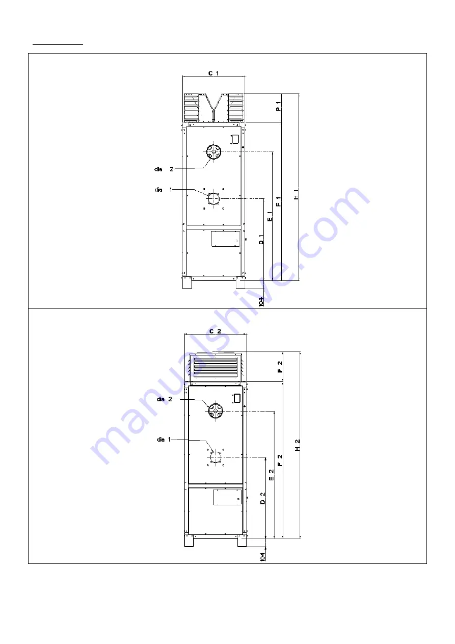
2.2 Dimensions
Vertical heater range
Figure 1a : unit with discharge nozzle
Front view
Figure 1b : unit with discharge plenum
Страница 1: ...it with the user or attached to the appliance or gas service meter after installation WARNING Improper installation adjustment alteration service or maintenance can cause property damage injury or de...
Страница 2: ...3 3 Electrical Connection 3 4 Ventilation Requirement 4 0 Installation 4 1 Location 4 2 Heater Clearances 4 3 Flue 4 4 Nozzled Heaters 4 5 Ducted Heaters 4 6 Filters 4 7 Controls 5 0 Commissioning 5...
Страница 3: ...f conformity are available from the Quality Control department at Ambi Rad Limited 1 3 CE Approval European Directives 1 3 1 Ambi Rad cabinet heaters have been fully assessed and tested and meet the f...
Страница 4: ...188 174 160 203 174 181 174 145 Smoke n 0 1 0 1 0 1 0 1 0 1 0 1 0 1 0 1 0 1 1 size 0 65 1 00 1 35 2 00 2 75 2 75 4 00 3 00 1 50 3 50 2 00 4 50 2 00 nozzle angle 60 60 60 60 45 45 60 2x 45 2x 45 2x 45...
Страница 5: ...4 61 50 89 49 88 50 90 50 89 47 84 49 87 49 88 Sound level 2 for guidance only dB A 52 52 53 53 59 61 61 65 63 67 Flue spigot outside diameter mm 125 125 150 178 178 178 178 223 223 223 Minimum flue h...
Страница 6: ...6 30 2 2 Dimensions Vertical heater range Figure 1a unit with discharge nozzle Front view Figure 1b unit with discharge plenum Front view...
Страница 7: ...7 30 Figure 1c Side view Figure 1d Figure 1e Figure 1f burner mounting flange air inlet air inlet...
Страница 8: ...8 30 Horizontal heater range Figure 2a Side view Figure 2b Front view...
Страница 9: ...804 2012 2012 2073 2073 2012 2012 inside dia 1 burner inlet 110 110 120 120 140 140 155 155 155 155 H1 2088 2088 2168 2168 2376 2378 2477 2477 2466 2466 H2 2164 2164 2114 2114 2400 2400 2395 2395 2334...
Страница 10: ...by the parameters of the installation i e number of heaters and length of pipeline 3 2 3 Please refer to the burner manual as to the limitations of the oil line and most suitable pipe diameters after...
Страница 11: ...ated heat input for high level outlet grills 3 4 4 Air Supply Requirement for Combustion and Ventilation table 4 Frame VCH Model Heat Input kW Low Level Grill cm High Level Grill cm 2 100 38 0 171 86...
Страница 12: ...s installed 4 0 Installation 4 1 Location 4 1 1 Ensure the structural elements of the building are adequate to carry the weight of the appliance and its ancillary components i e the flue system and th...
Страница 13: ...0 1000 Measured from front panel 4 3 Flue 4 3 1 Ambi Rad cabinet heaters must be connected to a flue system venting the products of combustion directly to outdoors Flue systems must be installed in ac...
Страница 14: ...ned in order to obtain the desired air distribution The louvres can be adjusted It is forbidden to close all louvres at a time as overheating could occur For safety reasons it is recommended to wear g...
Страница 15: ...ned 1 fully open 3 fully closed louvres all directions 2 fully open 2 fully closed louvres all directions for protection of fan motor and proper heater operation do not close all louvres at a time a m...
Страница 16: ...load when applying discharge ducting Duct outlets must be adjusted when necessary to meet the values mentioned in table 9 Table 9 Frame Model Nominal airflow Available outlet static pressure Motor loa...
Страница 17: ...adjusted when necessary to meet the values mentioned in table 9 4 5 5 Ducted air inlet on VCH HCH units The unit is designed so that it can be installed with inlet air ducts Vertical units Option 541...
Страница 18: ...556 III 400 500 541 4 end 691 1054 651 1014 541 5 top 541 7 bottom 1201 707 1161 667 541 6 rear 1082 707 1042 667 IV 600 700 541 4 end 1082 1201 1042 1161 541 5 top 541 7 bottom 1400 596 1360 556 541...
Страница 19: ...ails Filters must be inspected on a regular basis as dirty filters can affect the safe working of the unit For safety reasons it is recommended to wear gloves glasses when inspecting the filters Dirty...
Страница 20: ...end 1 standard 2 duct left 3 duct right 4 duct rear Figure 13a Overview of the VCH options Note When filters option 502 1 are required then the standard air intake panels must be replaced by the panel...
Страница 21: ...alibrated should be used at all times Pre Commissioning Checks Always ensure electrical safety and soundness of the oil installation before commencing and then proceed with the following checks a Ensu...
Страница 22: ...ust the primary air damper more open for less CO2 and more closed for more CO2 until the correct level has been obtained The CO2 level on site must be in the range of the figures given in table 2 1 h...
Страница 23: ...ich could lead to overheating of the heater The limiter will trip out Consequently the duct grilles will have to be opened Typical arrangement of oil storage tank single pipe system see figure 14 5 4...
Страница 24: ...Burner maintenance d Main fan and motor e Pulley and belts f Flue system g Control panel and electrical connections 6 2 Procedures Heat Exchanger a Access to the heat exchanger is made via the top rea...
Страница 25: ...ition of the belts for splits or fraying if one belt in any set appears to have worn excessively then change the whole set immediately DO NOT MIX BELTS OF DIFFERENT AGES OR BATCHES As the belts stretc...
Страница 26: ...Check burner motor Burner starts but goes to lockout Check oil supply Dirty cell Main oil cock open Air in oil line Photocell failure Air settings incorrect Oil valve faulty Change oil valve Purge oil...
Страница 27: ...not hold on main flame Insufficient air High inlet Pressure Fan limit stat Air inlets blocked Outlet nozzles closed Duct resistance too high Fan belts slipping Remove obstruction Clean filters Open lo...
Страница 28: ...ustion chamber CC air deflector 10 fixation plate HE 11 sliding bracket HE 12 over pressure relief panel 13 heat exchanger combustion chamber 14 side air deflectors 15 side inner skins 16 top side pan...
Страница 29: ...es 200 300 Contactor 60 61679 D910M5 sizes 400 500 600 700 800 Contactor 60 61679 D1210M size 1000 60 61703 02 04 size 400 60 61703 04 06 size 500 60 61703 05 09 size 600 60 61703 07010 sizes 700 800...
Страница 30: ...al BSEN 55014 Electromagnetic Compatibility BSEN 50165 Safety of Electrical Equipment BS 5440 Part 1 Specification Installation of Flues BS 5854 Code of Practice Flues Flue Structures BS 715 Metal Flu...