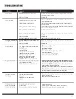
Amana HRV-150 Скачать руководство пользователя страница 23

23

TROUBLESHOOTING

Solutions

Causes

Problem

Dehumidistat control is set too low

Dehumidistat control is set too high

Sudden change in temperature

Storing too much wood for heating

Dryer vent exhaust is inside home

Poor air circulating near windows

Well sealed basement door is closed

Improper adjustment of dehumidistat con-
trol

Air is too dry

Air is too humid

Persistent condensation 
on window

Increase the desired level of humidity. Change ventilation mode from
continuous mode to standby.
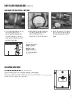
Balance HRV

Reduce the desired level of humidity. Combine this step with use of con-
tinuous exchange mode.

Wait until outside temperature stabilizes (winter). Heating will also
improve situation.

Store a majority of your wood outside. Even dried, a cord of wood con-
tains more than 20 gallons of water.

Arrange outside vent for dryer.

Open curtains or blinds. Bay or bow windows may require mechanical

method.

Balance HRV

Open the door or install a grill on the door.

Reduce the desired level of humidity. Combine this with the use of con-
tinuous exchange mode.
Balance HRV

-Clean exterior hoods or vents
-Remove and clean filter
-Remove and clean core
-Check and open grilles
-Have electrician check supply voltage at house
-Check duct installation
-Increase the speed of the HRV/ERV
-Have contractor balance HRV/ERV

-Locate the grilles high on the walls or under the baseboards, install

ceiling mounted diffuser or grilles so as not to directly spill the supply
air on the occupant (eg. Over a sofa)

-Turn down the HRV/ERV supply speed.  A small duct heater (1kw)

could be used to temper the supply air

-Placement of furniture or closed doors is restricting the movement of

air in the home

-If supply air is ducted into furnace  return, the furnace fan may need to

run continuously to distribute ventilation air comfortably

-Note: minimal frost build-up is expected on cores before unit initiates

defrost cycle functions

-Have HVAC contractor balance the HRV

-Tape and seal all joints
-Tape any holes or tears made in the outer duct covering 
-Ensure that the vapor barrier is completely sealed.

-1/4” (6mm) mesh on the outside hoods

is plugged

-Filters  plugged
-Core obstructed 
-House grilles closed or blocked
-Dampers are closed if installed
-Poor power supply at site
-Ductwork is restricting HRV/ERV
-Improper speed control setting
-HRV/ERV airflow improperly balanced

Poor Air Flows

-Poor location of supply grilles, the airflow

may irritate the occupant 

-Outdoor temperature extremely cold

Supply air feels cold

-HRV air flows are improperly 

balanced

-Malfunction of the HRV defrost 

system

HRV and / or Ducts
Frosting up

-Incomplete vapor barrier around 

insulated duct

-A hole or tear in outer duct covering

Condensation or Ice
Build Up in Insulated
Duct to the Outside

HRV out of balance

HRV out of balance

HRV out of balance

Содержание HRV-150

Страница 1: ...urnace or air handler operating at a higher static After installation the compatibility of the two pieces of equipment must be confirmed by measuring the airflow s of the Heat Recovery or Energy Recovery Ventilators by using the balancing procedure found in this manual It is always important to assess how the operation of any HRV ERV may interact with vented combustion equipment i e Gas Furnaces O...

Страница 2: ...ht of the ceiling to get cubic volume Then divide by 60 and multiply by 0 35 Example SQFT of House 1100 Basement 1100 Total SQFT 2200 Height of ceiling x 8 Cubic volume 17600 60 Maximum airflow required CFM 293 x 0 35 103 Always consult your local code for sizing requirements in your area Room classification Number of rooms CFM L s CFM Required Master bedroom x 20 cfm 10 l s Basement yes or no Bed...

Страница 3: ... maintenance free operation Seven 7 year limited warranty CORE Aluminum heat recovery core configured for an efficient cross flow ventilation Core is 9 x 9 229 x 229 mm with a 15 380 mm depth HRV 150D or 12 x 12 305 x 305 mm with a 15 380 mm depth HRV 200D Cores are manufactured to withstand extreme temperature variations FILTERS Two 2 Washable Electrostatic Panel Type Air Filters HRV 150D is 8 5 ...

Страница 4: ...Air From Inside 5TH port for recirculation defrost models only can be ducted or left open Airflow HRV 150D HRV 200D Model A B C D E HRV 150D 2 56mm 23 596mm 2 67mm 17 441mm 17 441mm HRV 200D 2 56mm 27 707mm 2 67mm 17 441mm 20 520mm Fan Performance Performance Data Model HRV 150D 72 69 HRV 200D 71 76 Apparent Sensible Effectiveness at 32ºF 0ºC Apparent Sensible Effectiveness at 13ºF 25ºC AIRFLOW CA...

Страница 5: ...y lubricated sealed bearings guarantee long life and maintenance free operation Seven 7 year limited limited warranty CORE Aluminum heat recovery core configured for an efficient cross flow ventilation Core is 9 x 9 229 x 229 mm with a 15 380 mm depth HRV 150 or 12 x 12 305 x 305 mm with a 15 380 mm depth HRV 200 Cores are manufactured to withstand extreme temperature variations FILTERS Two 2 Wash...

Страница 6: ...side Stale Air From Inside Airflow Model A B C D E HRV 150 2 56mm 23 596mm 2 67mm 17 441mm 16 413mm HRV 200 2 56mm 27 707mm 2 67mm 17 441mm 20 520mm Fan Performance Performance Data 6 Model HRV 150 72 69 HRV 200 71 76 Apparent Sensible Effectiveness at 32ºF 0ºC Apparent Sensible Effectiveness at 13ºF 25ºC AIRFLOW CAP cfm L s 0 4 on High Speed Power Volts 120 VAC Amperage HRV 150 1 5 Amps Total HRV...

Страница 7: ...enance free operation Seven 7 year limited warranty CORES Two 2 aluminum heat recovery cores configured for an efficient cross flow ventilation Core is 12 x 12 305 x 305 mm with a 15 380 mm depth Cores are manufactured to withstand extreme temperature variations FILTERS Two 2 synthetic high quality filters for better indoor air quality and clean air CONTROLS External three 3 position Low Stand By ...

Страница 8: ...re in WC Static Pressure Pa 200 00 240 00 280 00 320 00 360 00 19 00 0 00 38 00 57 00 76 00 94 00 114 00 123 00 142 00 162 00 5TH port for recirculation defrost models only can be ducted or left open Airflow Performance Data Model HRV 300D 92 91 Apparent Sensible Effectiveness at 32ºF 0ºC Apparent Sensible Effectiveness at 13ºF 25ºC AIRFLOW CAP cfm L s 0 4 on High Speed Power Volts 120 VAC Amperag...

Страница 9: ...tal control An on board diagnostic LED helps find problems quickly and efficiently For example the LED can be used to signal a broken or shorted electronic wall control wire Electronic air temperature probe gives this board accurate readings in order to minimize unnecessary defrost operation and the on board jumpers provide the user with the option of adjusting defrost time and sequence to optimiz...

Страница 10: ... higher than outdoor levels High humidity is a major cause of structure damage and IAQ problems such as mold and mildew 2 wire installation 4 wire installation 3 wire installation 2 wire installation DMFC REC DIGITAL MULTI FUNCTION WALL CONTROL WITH RECIRCULATION Control multiple functions of your HRV with one slimline wall control Two wire connec tion simplifies installation Use one control per H...

Страница 11: ...ht comes on when it s time to clean unit This function will let you know when it s time to check your filters and core To reset your filter light after you ve cleaned or replaced the filters just push the power but ton and restart the unit This will turn the light off and reset the clock for your filter check POWER On Off and Reset This function is to turn your unit on or off in the off posi tion ...

Страница 12: ...g its defrost mode the HRV may produce some condensation This water should flow into a nearby drain or be taken away by a condensate pump The HRV and all condensate lines must be installed in a space where the temperature is maintained above the freezing point A P trap should be made in the drain line This will prevent odors from being drawn back up into the unit MOUNTING LOCATION The HRV must be ...

Страница 13: ...barrier must be completely sealed to outer wall and the HRV using tape and or caulking A good bead of high quality caulk ing preferably acoustical sealant will seal the inner flexible duct to both the HRV port and the weatherhood prior to clamping To minimize air flow restriction the flexible insulated duct that connects the two outside weatherhoods to the HRV should be stretched tightly and be as...

Страница 14: ... elbows as possible Forty five degree are preferred to 90º elbows Use Y tees instead of 90º elbows whenever possible All duct joints must be fastened with screws or duct sealant and wrapped with a quality duct tape to prevent leakage Aluminum foil duct tape is recommended Galvanized ducting from the HRV to the living areas in the house is recommended whenever possible although flexible duct can be...

Страница 15: ...rilles be completely opened at first and then adjusted later as needed Dedicated Installation for Existing Home non forced air heating cooling system 1 Begin with the duct collar marked Exhaust Air In Slide a short piece 12 of flexible duct over the duct collar Using duct tape tape the flexible duct to the collar Run the flexible ducting to the main rigid duct trunk line which connects to the rema...

Страница 16: ... EXAMPLES Example diagram only duct configuration may change depending on model It is the responsibility of the installer to ensure all ductwork is sized and installed as designed to ensure the system will perform as intended All air movement devices have a performance curve The amount of air CFM that an HRV ERV will deliver is directly related to the total external static pressure E S P of the sy...

Страница 17: ...from key areas of home Exhaust Air from various parts of home i e bathrooms if required kitchens if required NOTES 1 Furnace blower may be required to operate when HRV ERV is on to provide good air distribution 2 Weatherhood arrangement is for drawing purposes only 6 2m minimum separation recommended 18 460mm above grade minimum 3 Due to the differences in pressure between the HRV ERV and the equi...

Страница 18: ...ously or interlocked with HRV ERV 2 A minimum separation of 39 inches 1m is recommended between the two direct connections 3 The exhaust air connection should be upstream of the supply air connection to prevent exhausting any fresh air 4 Weatherhood arrangement is for drawing purposes only 6 2m minimum separation recommended 18 460 mm above grade minimum 5 Due to the differences in pressure betwee...

Страница 19: ...nace should be set to run continuously or interlocked with HRV ERV 2 The exhaust air connection should be upstream of the supply air connection to prevent exhausting any fresh air 3 Weatherhood arrangement is for drawing purposes only Six feet 2m minimum separation recommended Eighteen inches 460 mm above grade minimum 4 Due to the differences in pressure between the HRV ERV and the equipment it i...

Страница 20: ...allation may limit the amount of straight duct The Pitot tube should be connected to a magnehelic gauge or other manometer capable of reading from 0 to 0 25 in 0 62 Pa of water preferably to 3 digits of resolution The tube coming out of the top of the pitot is connected to the high pressure side of the gauge The tube com ing out of the side of the pitot is connected to the low pressure or ref eren...

Страница 21: ...vious steps to adjust the Exhaust Air Out damper if needed B Measure here Measure here 18 457 mm 18 457 mm To avoid airflow turbulence and incorrect readings the airflow velocity should be measured on steel ducting a minimum of 18 457 mm from the unit or elbow and before any transition ELECTRONIC BALANCING MOTORS HRV 150D 200D only Motors will be factory set at their full potential depending on sp...

Страница 22: ...oing any repairs or mainte nance a Open access door b Carefully grip ends of core and pull evenly out ward Core may be snug but will slide out of the channel c Once removed from the cabinet remove filters d Wash core in warm soapy water do not use dishwasher e Install the clean filters f Install clean core To Install the Clean Core and Filters a First mount the bottom flange of the core guide into...

Страница 23: ...V ERV Locate the grilles high on the walls or under the baseboards install ceiling mounted diffuser or grilles so as not to directly spill the supply air on the occupant eg Over a sofa Turn down the HRV ERV supply speed A small duct heater 1kw could be used to temper the supply air Placement of furniture or closed doors is restricting the movement of air in the home If supply air is ducted into fu...

Страница 24: ... COOLING SYSTEM WIRE JOINT DMFC REC This control is not polarity sensitive therefore you may connect any wire to either positive or negative connection DMFC REC or DMFC RT 15M MD 2W or CT 30M MD 4W DMFC This control is not polarity sensitive therefore you may connect any wire to either positive or negative connection 2 wire connection RT 15M Connect to positive and negative connections on elec tri...

Страница 25: ...ELECTRICAL CONNECTIONS CONT D Custom defrost mode jumper selection 3 position mode selection switch Accessory Control Contact Open Closes contact when HRV ERV is ON OFF Diagnostic LED U Air Quality Sensor ...

Страница 26: ...26 ...

Страница 27: ...27 ...

Страница 28: ...ns components and specifications Item 402950 Rev 1 Rev Date 11022006 United States 1712 Northgate Blvd Sarasota FL 34234 Phone 800 747 1762 941 309 6000 Fax 800 487 9915 941 309 6099 www fantech net info fantech net Canada 50 Kanalflakt Way Bouctouche NB E4S 3M5 Phone 800 565 3548 506 743 9500 Fax 877 747 8116 506 743 9600 www fantech ca info fantech ca ...

Отзывы: