2
VAPOMATIC ANESTHETIC VAPORIZER
INSTALLATION
:
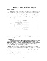
The Vapomatic is normally mounted on the back bar of an anesthetic machine or
in any case it should be solidly mounted to a rigid structure in an upright position. Two
tapped holes in the rear mounting face (1/4”-20) are provided for mounting. Since these
are “blind” holes of 5/16” depth, screws of a proper length must be used so that they may
be tightened before bottoming. A suggested mounting arrangement which allows
flexibility in coping with various structure thicknesses is shown in Fig. 1
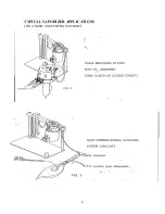
In some cases it may be desirable to mount the Vapomatic on a table or horizontal
surface. A
¼
” -20 tapped mounting hole is provided for this purpose in the center bolt at
the bottom of the vaporizer.
CONNECTIONS
:
Standard connections are (facing the front of the Vapomatic) left side, inlet, cage
mount/23mm Male standard taper, and right side, outlet, cage mount/23mm Female
standard taper. Normally, in veterinary use, mating connectors having tubing adapters are
used, so that rubber tubing can be connected to the gas supply, either the flow meter
common outlet, or the outlet terminal of the gas machine.
CAUTION
:
The vaporizer inlet should
not
be connected downstream of the flush
valve, otherwise excessive back pressure may be reflected back into the flow meters and
other parts of the circuit when the flush valve is activated, possibly causing bursting of
tubing or other components.
The vaporizer outlet must be connected to the patient via the outlet of the gas
machine or directly to the breathing circuit which would be, to the CO2 absorber, or to
the non-rebreathing patient circuit.


