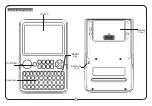
Advanced Setup
MOUNT AND WIRE
A
Select a mounting position and location.
• Mount the translator at least 5 feet from the Control Panel’s
receiver.
• Do NOT mount the translator in a metal can or on a metal
surface.
• Verify adequate RF signal strength at the panel before
permanently mounting.
B
Connect the power supply to the translator using either the
supplied barrel connector or flying leads.
• Rotate the barrel plug down to the right so the wires exit the
enclosure through the strain relief area.
• Ensure the backup battery connector is plugged into the
translator.
• Do not connect to a receptacle controlled by a switch.
Ne pas se connecter à une prise contrôlée par un interrupt-
eur.
• In the United States, the transformer must be secured to
an outlet.
• In Canada, the transformer must NOT be secured to the
outlet.
TRANSLATOR CONFIGURATION
A
Select the brand of panel that the translator must talk to
using the “PANEL SELECT” knob.
B
Select the brand of sensors that the translator must listen to
using the “SENSOR SELECT” knob.
C
Sensor Configuration:
The translator must learn the sensors
that are to be translated or repeated.
a)
Press and release the CONFIGURE button to enter
translator configuration mode. The yellow LED will turn on
when translator configuration mode is entered.
b) Tamper or trip all sensors to be included in the system. The
translator beeps for each sensor that is included in the
system.
c)
Press CONFIGURE button to exit translator configuration
mode. The yellow LED will turn off when the translator
configuration mode is exited.
• Configuration mode ends automatically when the cover
is closed or 30 minutes after the last action.
• Sensors may be enrolled directly into the panel while in
configuration mode.
• Configuration mode is locked out 24 hours after power up.
To re-enable configuration mode, the translator must be
power cycled by removing both 12VDC input power and
backup battery for at least 5 seconds.
• When re-entering translator configuration mode, previously
configured sensors are retained. There is no need to re-
configure every sensor if the intention is to add a sensor.
• Configuration data is retained even if both the 12VDC
input power and battery backup power are lost.
• When both the panel and sensor selection knobs are set to
the same brand the translator will act as a repeater.
PANEL ENROLLMENT
A
Enroll
Translator into Panel:
• Trip the cover tamper to enroll the translator into the
panel.
-or-
•
Enter ID into panel. The translator’s base ID is printed on
the bar code label.
(For
Honeywell® and 2GIG®
panels, select loop 1)
PANEL ENROLLMENT (continued)
B
Enroll Sensors
into panel:
• With the translator cover open, tamper or trip each sensor
to send an enrollable transmission to the panel.
• Finish setup of each sensor at the panel.
Below are guidelines on how to enroll the translator and
sensors into your panel. Refer to the panel installation manual
for complete panel instructions.
Interlogix ® (formerly GE ®)
A
Translator enrollment:
a) Enter Learn Sensor mode.
b)
At the Trip Sensor prompt: Trip the translator’s cover
tamper to enroll the translator into the panel.
c)
Select Group 13 instant perimeter
B
Sensor enrollment:
a) Enter Learn Sensor mode.
b)
At the Trip Sensor prompt: Tamper each sensor to
enroll it. If the sensor does not have a tamper switch trip
the sensor with translator cover open to enroll it.
• For the first 24 hours after power-up, all Interlogix
sensor trips will transmit a temporary tamper for
enrollment if the translator cover is open.
c) Set up the sensor for the desired behavior.
Honeywell ®
A
Translator enrollment:
a) Enter Programming mode.
• Zone Type: 3 (Perimeter).
• Input Type: 3 (Supervised RF).
b)
When prompted:
• Trip the translator’s cover tamper multiple times.
-or-
• Enter the translator’s ID number, which is printed on
the unit.
c)
Use loop 1 for translator itself.
B
Sensor enrollment:
a) Enter Programming mode.
• Set up the sensor for the desired behavior.
b)
When prompted: Perform the typical Honeywell
enrollment sequence.
• The translator does not support multiple loops on
Honewell sensors. Ony one loop may be used.
2GIG ®
A
Translator enrollment:
a) Enter RF enrollment mode
• Sensor Type: (03) perimeter
• Equipment Code: For GC3, use (0873) Take-345.
For other panels, (0862) DW10-345 may also be used.
b)
At “Enter RF Serial Number”:
• Press SHIFT, Learn, then trip the translator cover
tamper to enroll the translator
-or-
• Enter the translator’s ID number, which is printed on
the unit.
c)
Equipment Age: (0) new
d)
Loop Number: (1)
B
Sensor enrollment:
a) Enter RF enrollment mode.
b) Set up the sensor for the desired behavior.
c)
When prompted, perform the typical 2GIG enrollment
sequence.
1
2
3
3
3


