background image

1

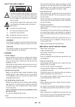
SAFETY RELATED SYMBOLS

CAUTION

RISK OF ELECTRIC SHOCK

DO NOT OPEN

This symbol, wherever used, alerts you to the pre-
sence of un-insulated and dangerous voltages with-
in the product enclosure. These are voltages that
may be sufficient to constitute the risk of electric
shock or death.

Protective Ground Terminal

AC mains (Alternating Current)

Hazardous Live Terminal

ON:

Denotes the product is turned on.

This symbol, wherever used, alerts you to impo-
rtant operating and maintenance instructions.
Please read.

OFF:

Denotes the product is turned off.

WARNING

Describes precautions that should be observed to
prevent the possibility of death or injury to the user.

CAUTION

Describes precautions that should be observed to
prevent damage to the product.

Power Supply

Ensure that the mains source voltage (AC outlet)
matches the voltage rating of the product. Failure
to do so could result in damage to the product and
possibly the user.

Unplug the product before electrical storms occur
and when unused for long periods of time to reduce
the risk of electric shock or fire.

External Connection

Always use proper ready-made insulated mains
cabling (power cord). Failure to do so could result
in shock/death or fire. If in doubt, seek advice from
a registered electrician.

Do Not Remove Any Covers

Within the product are areas where high voltages
may present. To reduce the risk of electric shock do
not remove any covers unless the AC mains power
cord is removed.

Covers should be removed by qualified service
personnel only.

No user serviceable parts inside.

Fuse

To prevent fire and damage to the product, use only

the recommended fuse type as indicated in this
manual. Do not short-circuit the fuse holder. Before
replacing the fuse, make sure that the product is
OFF and disconnected from the AC outlet.

Protective Ground

Before turning the product ON, make sure that it is
connected to Ground. This is to prevent the risk of
electric shock.

Never cut internal or external Ground wires. Likewise,
never remove Ground wiring from the Protective
Ground Terminal.

Operating Conditions

Always install in accordance with the manufacturer's
instructions.

To avoid the risk of electric shock and damage, do
not subject this product to any liquid/rain or moisture.
Do not use this product when in close proximity to
water.

Do not install this product near any direct heat source.

Do not block areas of ventilation. Failure to do so
could result in fire.

Keep product away from naked flames.

IMPORTANT SAFETY INSTRUCTIONS

Read these instructions

Follow all instructions

Keep these instructions. Do not discard.

Heed all warnings.

Only use attachments/accessories specified by the
manufacturer.

Power Cord and Plug

Do not tamper with the power cord or plug. These are
designed for your safety.

Do not remove Ground connections!

If the plug does not fit your AC outlet seek advice from
a qualified electrician.

Protect the power cord and plug from any physical
stress to avoid risk of electric shock.

Do not place heavy objects on the power cord. This
could cause electric shock or fire.

Cleaning

When required, either blow off dust from the product
or use a dry cloth.

Do not use any solvents such as Benzol or Alcohol.
For safety, keep product clean and free from dust.

Servicing

Refer all servicing to qualified service personnel only.

Do not perform any servicing other than those instruc-
tions contained within the User's Manual.

WARNING

Содержание X34SW

Страница 1: ...LTO R www altoproaudio com Version 2 0 Dec 2002 English User s Manual 3 WAY STEREO CROSSOVER PLUS SUBWOOFER X34SW ...

Страница 2: ...y the recommended fuse type as indicated in this manual Do not short circuit the fuse holder Before replacing the fuse make sure that the product is OFF and disconnected from the AC outlet Protective Ground Before turning the product ON make sure that it is connected to Ground This is to prevent the risk of electric shock Never cut internal or external Ground wires Likewise never remove Ground wir...

Страница 3: ...ity of our job we d like to share with you our work and our dreams pay attention to your and your suggestions comments Following this idea we create our products and we will create the new ones From our side we guarantee you and we will guarantee you also in future the best quality the best fruits of our continuous researches and the best prices Our LTO Active Crossover is the result of many hours...

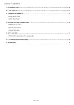
Страница 4: ...IST 4 3 CONTROL ELEMENTS 4 3 1 The Front Panel 3 2 The Rear Panel 4 INSTALLATION CONNECTION 6 4 1 Mains Connection 4 2 Audio Connection 4 3 Rack Mounting 5 APPLICATION 7 5 1 X34SW 3 Way Stereo Plus Subwoofer 6 TECHNICAL SPECIFICATIONS 8 7 WARRANTY 9 ...

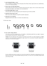
Страница 5: ... Servo balanced XLR connectors for all inputs and outputs 3 CONTROL ELEMENTS 3 1 The Front Panel 1 Power Switch Turn the power on or off 2 L M H Output Gain Controls These knobs are used to attenuate or boost the Low Mid High frequencies output 3 30Hz Low Cut Switch Engage this button to add a 30Hz Low Cut filter into the input signal path 4 M H CROSSOVER FREQ Control Subwoofer output gain adjustm...

Страница 6: ...nob adjusts the crossover frequencies of the Subwoofer way from 50Hz to 250Hz 8 Subwoofer Output Gain Control This knob is used to attenuate or boost the subwoofer output gain 9 Subwoofer Low Cut Switch Engage this button to add a 30Hz Low Cut filter in the Subwoofer way Your unit may have the AC voltage selector 115V 60Hz or 230V 50Hz built into the Fuse Holder To change pull fuse holder out and ...

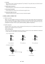
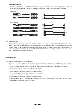
Страница 7: ...ATION CONNECTION 4 1 Mains Connection Please ensure that the LTO X34SW Active Crossover is set to the correct supply voltage before plug the ging power cord into the wall outlet use the same fuse as marked on the fuse holder at the AC connection socket power The mains connection of the LTO X34SW Active Crossover is made by using the enclosed mains cord and a standard IEC receptacle It meets all of...

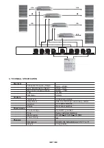
Страница 8: ...t the Mid frequencies signal to the power amplifier 4 Output the High frequencies signal to the power amplifier 6 Power up the X34SW first then the power amplifier to run the system While powered off please ensure the power amplifier is turned off first then the X34SW 5 APPLICATION 5 1 X34SW 3 Way Stereo Plus Subwoofer To get such a typical application configure your system and connect the wires i...

Страница 9: ... High continuously variable Front panel switches Front panel switches Power supply Connector type 3 pole IEC grounded Servo controlled stabilized 8W Type Mains supply Power Rating 95 120V 210 240V 60 50Hz Physical Dimensions 483 W 194 5 D 44 H mm 19 7 7 1 7 Weight 3 0 kg 6 62lb INPUT 2 WOOFER HIGH OUT 1 MID OUT 1 INPUT 1 LOW OUT 1 HIGH OUT 2 MID OUT 2 LOW OUT 2 INPUT 2 SUB WOOFER HIGH OUT 1 MID OU...

Страница 10: ... LTO of 1 year from the purchase date if you have completed the Warranty Registration Card in time 3 3 During the warranty service may repair or replace this product at its own option at no charge to you for LTO parts or for labor in accordance with the right side of this limited warranty 3 4 This warranty does not apply to the damages to this product that occurred as the following conditions Norm...

Страница 11: ...ll rights reserved to ALTO Mobile Due to continued development in response to customer feedback product features specifications and or internal external design may be changed without prior notice No photocopying translation or reproduction of any part of this user manual is allowed without prior written permission Copyright 2004 Seikaku Technical Group Limited c NF00861 1 0 ...

Отзывы: