


Installation
IP 705 Manual
21
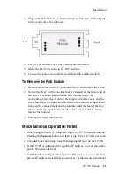
3. Plug in the PoE Module as illustrated below. The side with four pins
in the
center
faces the right side.
4. Put the PoE module cover back, and tighten the screw.
5. Move the DC/PoE switch to the PoE position.
6. Connect the phone to an AltiGen-certified PoE-enabled switch.
To Remove the PoE Module
1. Remove the screw on the PoE Module cover, and remove the cover.
2. Notice the “feet” on the two tabs that are located on the lower end of
the cover. Use these feet to lift the PoE module out of the
compartment, like this: Holding the upper end of the cover, slip the
cover into either the right side or left side of the module compartment,
between the compartment and the module, until the feet of the two
tabs is under the module (the inside of the cover should be facing
toward the module).
3. Pull up to remove the module.
Miscellaneous Operation Notes
• When using #26 and #27 to log out / log in, the IP 705 must be onhook.
Pressing the
Speaker
button and then using #26 or #27 will not work.
• Two dial tones are always heard when going offhook on the IP 705.
• If the IP 705 is configured for a public IP address, you can call other
public IP address devices.
• If the IP 705 is configured for a private IP address, you can call other
private IP address devices that you can “see” or that are on your subnet.
Right
Left
Содержание IP 705
Страница 1: ...IP 705 Phone Administration Manual 04 2006 4290 0014 5 0A ...
Страница 5: ...IP 705 Manual iii Index 63 ...
Страница 10: ...viii IP 705 Manual ...
Страница 50: ...40 IP 705 Manual ...
Страница 60: ...LCD Messages 50 IP 705 Manual ...