Instruction manual 91/104 V9.2
Commissioning
Output Summ1
Minimum Maximum Units of measure
-100,00
+100,00
%
Percentage value of the summation output 1 of the summing block. This number represents the sum of entry 1 and entry 2.
Output Summ2
Minimum Maximum Units of measure
-100,00
+100,00
%
Percentage value of the summation output 2 of the summing block. This number represents the sum of entry 3 and entry 4.
Output Summ3
Minimum Maximum Units of measure
-100,00
+100,00
%
Percentage value of the summation output 3 of the summing block. This number represents the sum of the summation output 1 and the
summation output 2 (if they have not been deactivated with the digital input).
PID Speed Loop
Set of parameters to adjust the time constants of the PID adjustment loop on the speed.
NOTE:
random change in these parameters can lead to a worsening of the drive’s performance. It is advisable not to change these
values unless strictly necessary and possibly to contact the ALTER technical office for explanations and clarifications. Please note
that it is possible to return the parameters to the value prior to the change simply by removing the voltage from the services and
then returning it or using the "Restore“ menu (see page 40), always allowed to NOT have already saved the parameters with the
"Memo Parameters“ menu (see page 40).
Proport. Gain 1 / 2
Minimum Maximum Units of measure
0
999.00
-
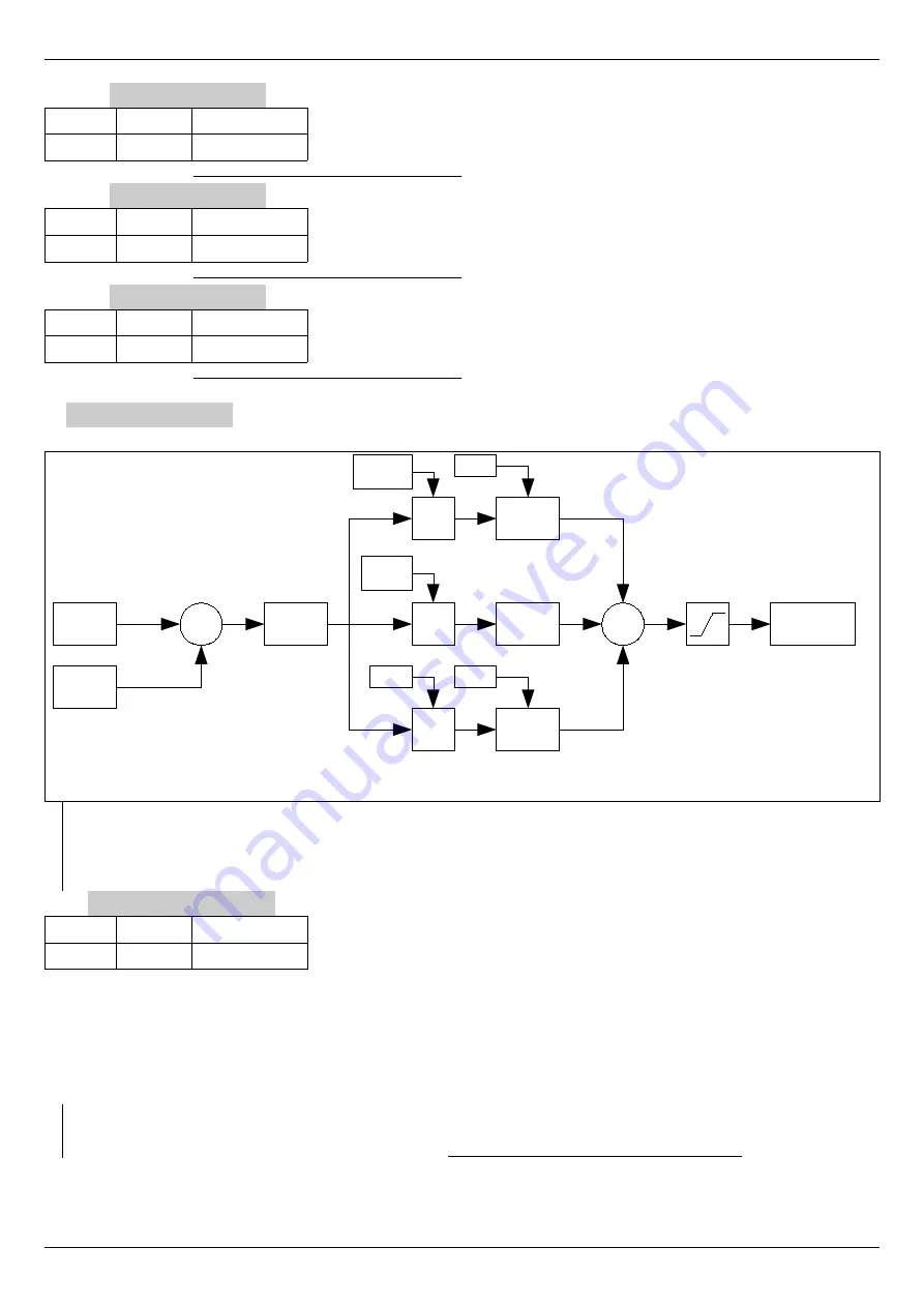
This parameter modifies the Proportional time constant of the speed loop (see drawing 20). Increasing this value makes the motor
speed more precise than the reference from the outside, but the loop can become unstable (you can hear the motor vibrate).
Conversely, by decreasing this parameter the motor is more stable but becomes slower in following the speed reference that is given
from the outside.
It is recommended to change this parameter in small steps and test the motor reaction before further changes. When you have found
the right parameter that meets your needs, you can memorise the variations with the “Memo Parameters“ menu (see page 40) and not
before; in this way it will always be possible to return to the previous situation.
NOTE:
To select the gain in use (Gain 1 or Gain 2) the digital input to "
Gain
Selection
“ is used; the Gain 1 is used if the input
that controls the switching of the gain is at level 0, instead the Gain 2 is used if it is level 1. The digital input that controls
switching is set in the "Dig.Inp. X Dest“ menu (see page 43); Under standard conditions this input is the DI3.
Alter Elettronica s.r.l.
53
Drawing 20: Speed loop
Speed
Demand
Speed
Feedback
-
Speed
Error
P
P gain 1 /
P gain 2
I
I gain 1 /
I gain 2
D
D gain
Filter
PB
Anti
Windup
Filter
PB
+
Limit
Torque
Demand
Dcomp
Pcomp


