14
DISTRIBUTION AMPLIFIER/ZONE MIXER/MIC SPLITTER DA-410.
This multipoint level circuit indicates the highest level reached inside the unit output circuits
and warns the operator about possible problems. When the level indicator lights green, the
internal level has reached -20 dBv. (signal present led). Should any internal level is near overload
(+15 dBv) the level indicator lights on red to warn the security limit has been surpassed. On that
case the unit has a 6 dB extra dynamic reserve or headroom. In order to correct this problem
should lower the level of that output or decreases the input signal.
OUTPUT LEVEL CONTROL
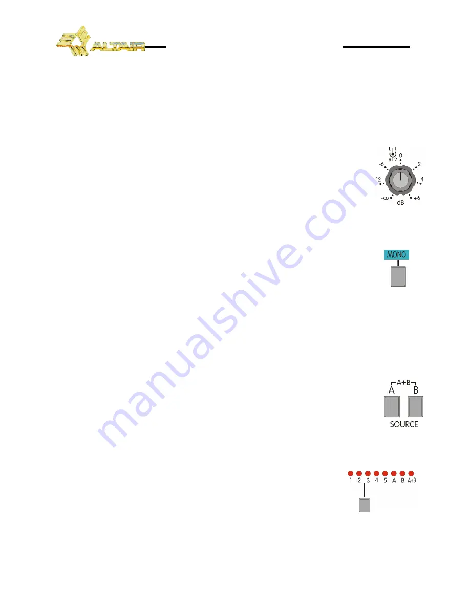
Each unit stereo output (1, 2, 3, 4 & 5) provides a gauged input level control
between -
∞
and +6 dB placed at the front panel. This output level control is rotary
and concentric. Internal knob is dedicated to control the Left (L) output level and the
external knob for Right (R) output level. When operating in mono mode, this
corresponds to outputs 1, 3, 5, 7, 9 and 2, 4, 6, 8 and 10 respectively.
MONO SIGNAL SWITCH
Each of the five sections incorporates a MONO switch that mix L and R incoming
signals routing it to the relevant outputs at the selected front panel output levels. When
this switch is not depressed, the L and R outputs are independent (stereo).
This switch allows adapting the stereo signals to monophonic equipment, and
equally duplicate the monophonic input signals for stereo equipments.
NOTE:
If the input signal is monophonic, it's say, the input signal only are connected to L or R, upon
pressing the MONO switch, it will produce an attenuation of 6 dB in each one of the outputs. In
order to avoid this signal loss, it is advisable duplicate the inputs with an external bifurcation or
compensate it with the output gain controls.
INPUT SIGNAL SELECTOR
The input signal selector placed at the front panel, allow us select the input signal
that we will obtain at the output. When the A switch is depressed, we will obtain in the
stereo output (1, 2, 3, 4, or 5) the A stereo input signal. If we depressed the B switch, we
will obtain the B stereo input signal in the stereo output, and if we pressed the two at
the same time, we will obtain the sum of the two stereo input signals in L and R outputs
(the two outputs will have the same signal determined by the input level controls).
MONITOR SIGNAL SELECTOR
The monitor signal selector, placed at the front panel, allow us to
choose from any input or output stereo signals for monitoring purposes.
Selection is made sequentially by a momentary push button. This selector
allow us to monitor (either by means of the miniature speakers, or the
headphone output), all the outputs and inputs (A and B) and the sum of the
two stereo inputs (A+B). Upon turn on the unit, the monitor signal selector is placed automatically
in the output 1 position.


