P846/EN FD/D
Firmware Design
(FD) 9-14
MiCOM P846
P4091ENa
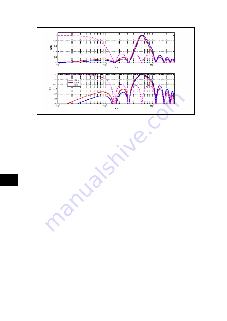
Figure 5: Frequency response of the DLO Kalman filter
1.4.6
Fourier filtering
All backup protection and measurement functions use one cycle fourier digital filtering to
extract the power frequency component. This filtering is performed on the main processor
board.
1.4.6.1 Programmable scheme logic
The purpose of the programmable scheme logic (PSL) is to allow the relay user to configure
an individual protection scheme to suit their own particular application. This is achieved
through the use of programmable logic gates and delay timers.
FD
The input to the PSL is any combination of the status of the digital input signals from the
opto-isolators on the input board, the outputs of the protection elements, e.g. protection
starts and trips, control inputs, function keys and the outputs of the fixed protection scheme
logic. The fixed scheme logic provides the relay’s standard protection schemes. The PSL
itself consists of software logic gates and timers. The logic gates can be programmed to
perform a range of different logic functions and can accept any number of inputs. The timers
are used either to create a programmable delay, and/or to condition the logic outputs, e.g. to
create a pulse of fixed duration on the output regardless of the length of the pulse on the
input. The outputs of the PSL are the LEDs on the front panel of the relay and the output
contacts at the rear.
The execution of the PSL logic is event driven; the logic is processed whenever any of its
inputs change, for example as a result of a change in one of the digital input signals or a trip
output from a protection element. Also, only the part of the PSL logic that is affected by the
particular input change that has occurred is processed. This reduces the amount of
processing time that is used by the PSL. The protection and control software updates the
logic delay timers and checks for a change in the PSL input signals every time it runs.
This system provides flexibility for the user to create their own scheme logic design.
However, it also means that the PSL can be configured into a very complex system, and
because of this, setting of the PSL is implemented through the PC support package MiCOM
S1.
Содержание MiCOM P846
Страница 2: ......
Страница 4: ......
Страница 5: ...Safety Section P846 EN SS H11 SS SAFETY SECTION...
Страница 6: ...P846 EN SS H11 Safety Section SS...
Страница 8: ...P846 EN SS H11 Safety Section SS 2 SS...
Страница 16: ...P846 EN IT D Introduction MiCOM P846 IT...
Страница 18: ...P846 EN IT D Introduction IT 1 2 MiCOM P846 IT...
Страница 26: ...P846 EN TD D Technical Data MiCOM P846 TD...
Страница 38: ...P846 EN GS D Getting Started MiCOM P846 GS...
Страница 58: ...P846 EN ST D Getting Started MiCOM P846 ST...
Страница 60: ...P846 EN ST D Settings ST 4 2 MiCOM P846 ST...
Страница 78: ...P846 EN OP D Operation MiCOM P846 OP...
Страница 104: ...P846 EN OP D Operation OP 5 26 MiCOM P846 OP...
Страница 106: ...P846 EN AP D Application Notes MiCOM P846 AP...
Страница 108: ...P846 EN AP D Application Notes AP 6 2 MiCOM P846 AP...
Страница 122: ...P846 EN AP D Application Notes AP 6 16 MiCOM P846 AP...
Страница 124: ...P846 EN PL D Programmable Logic MiCOM P846 PL...
Страница 126: ...P846 EN PL D Programmable Logic PL 7 2 MiCOM P846 PL...
Страница 144: ...P846 EN MR D Measurements and Recording MiCOM P846 MR...
Страница 146: ...P846 EN MR D Measurements and Recording MR 8 2 MiCOM P846 MR...
Страница 160: ...P846 EN FD D Firmware Design MiCOM P846 FD...
Страница 182: ...P846 EN CM D Commissioning MiCOM P846 CM...
Страница 228: ...P846 EN CM D Commissioning CM 10 46 MiCOM P846 CM...
Страница 230: ...P846 EN MT D Maintenance MiCOM P846 MT...
Страница 232: ...P846 EN MT D Maintenance MT 11 2 MiCOM P846 MT...
Страница 238: ...P846 EN TS D Troubleshooting MiCOM P846 TS...
Страница 240: ...P846 EN TS D Troubleshooting TS 12 2 MiCOM P846 TS...
Страница 252: ...P846 EN SC D SCADA Communications MiCOM P846 SC...
Страница 272: ...P846 EN SG D Symbols and Glossary MiCOM P846 SG...
Страница 280: ...P846 EN SG D Symbols and Glossary SG 14 8 MiCOM P846 SG...
Страница 282: ...P846 EN IN D Installation MiCOM P846 IN...
Страница 284: ...P846 EN IN D Installation IN 15 2 MiCOM P846 IN...
Страница 293: ...Installation P846 EN IN D MiCOM P846 IN 15 11 7 P846 CASE DIMENSIONS Figure 3 Case dimensions IN...
Страница 295: ...Installation P846 EN IN D MiCOM P846 IN 15 13 P1756ENa IN Figure 5 Model B with 32 output contacts and 24 digital inputs...
Страница 296: ...P846 EN IN D Installation IN 15 14 MiCOM P846 IN...
Страница 297: ......


