3
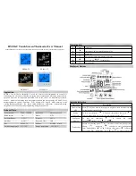
Red = controller requests heat supply
Green = energy economizing mode (night temperature decrease mode)
4. Indicators
Existing load
Turning knob position to be adjusted
Associated number of blinks after setting
0 – 1150 W
(0 – 5A)
1
1150 – 1350 W
(5 – 6A) 2
2
1350 – 1600 W
(6 – 7A) 3
3
1600 – 1850 W
(7 – 8A)
4
1850 – 2050 W
(8 – 9A) 5
5
2050 – 2300 W
(9 – 10A) 6
6
Load setting table
knob. Once this has been done, a PZ 1 screwdriver must to be applied to loosen the screw that is visible now. After that, the controller cap can be removed along
with the frame. After its electrical connection and installation in an UP box, the housing can be closed again in inverse order. The sensor carries line voltage poten-
tial and may only be extended by means of an H05VV-F compliant cable. The double insula tion required by EN 60730-1 needs to be observed at the connection
point too. Care must be taken to ensure that the sensor line is not laid in parallel to line voltage carrying cables or lines. Where parallel laying cannot be avoided, a
shielded line must be used and the shielding be connected to the sensor mass. In order to ensure the easy replacement of a defective sensor, the sensor including
its line needs to be laid inside an empty conduit in a replace able manner. The protecting sleeve, type THF, serves for the closing of the empty conduit that has been
concealed in the related surface structure (see section 6., Accessories). The sensor must, in order to obtain an optimal distribution of the heat in the floor, be positi-
oned centrically between two heating conductors. With warm-water heated surfaces, normally closed valves are to be used. Possibly required temperature limiters
need to be installed in addition.
3.1. Limitation of the setting range
The setting range can be limited by removing the pin that exists underneath of the
adjusting knob and by adjusting the setting pins as needed
(red pin for maximum and blue pin for minimum possible setting).
After that, the pin needs to be plugged in again in order to fix the limits.
Pin for the setting of
the max.
temperature value
Pin for the setting of
the min.
temperature value
Controller (50 x 50) with standard type frame
Controller (50 x 50) with sample frame and intermediate frame
Controller (55 x 55) with sample frame
Switch off the device. Use the adjusting
knob in accordance with the table here-
after for the setting of the desired load.
Remove the turning knob and the cover (screwed)
without misadjusting the previously adjusted value.
Use an isolate screwdriver to turn the potentiometer.
In anticlockwise direction until to its stop. Switch on the
device. After that, check the actual load setting on the
basis of the number of blinks.
3.3 Adjustment of the floor temperature limitation
This adjustment is to be made after completion of the load setting procedure
described in above sub-section 3.2. Turning the internal potentiometer in
compliance with the scale shown on the right / in the housing cover enables
to limit the floor temperature to the desired max. value. Factory setting: 50°C.
3.2 Load adjustment
The FETR 101.745 has been equipped with an internal sensor that serves for the regulation of the room temperature. The load switched by the controller causes an in-
ternal warming that impinges on the sensor. To compensate this influencing, a corresponding load setting needs to be made. Ex factory, the controller has been adjusted
to a load of 6 to 7A (1350W up to 1600W).
Load setting procedure – Caution: the setting takes place with the system in live condition!
When the device is fully assembled and switched off, set the temperature setting button for the corresponding load according to the load setting table. Remove the
rotary knob without adjusting the rotary knob and unscrewing the housing cover. Now use an insulated screwdriver to turn the internal potentiometer counterclock-
wise until it stops.
Only now switch on the device
(if the device is already switched on there is no activation of the load setting). The green lamp starts to blink. To
check the load setting, compare the number of flashes with the values in the load setting table. The number of flashes is repeated, interrupted by small pauses (ap-
prox. 2-3 seconds). If the load setting is correct, the limit temperature of the floor must then be set using the internal potentiometer.