


21
4. Click “Reset EQ”, all the equalizers of the
current channel are reset to the initial state:
the frequency is evenly distributed, the
input Q value is 2.515, the output Q value is
2.201, and the gain is 0.0 dB.
5. Click “P.EQ”, a warning dialog box appears,
indicating “Are you sure you want to switch
from the G.EQ mode to the P.EQ mode?”,
press “Confirm” to switch to the “P.EQ”
mode. Click “G.EQ”, a warning dialog box
appears, indicating “Are you sure you
want to switch from the P.EQ mode to the
G.EQ mode?”, Press “Confirm” to switch
to the “P.EQ” mode. In the P.EQ mode,
the frequency, Q value, and gain can be
adjusted, while in the G.EQ mode, the
frequency and Q value are fixed and only
the gain of the EQ can be adjusted.
Setting the Channel Phase and
Volume
1. Phase: Click the positive phase icon “
” or the negative phase icon “ ” to switch
between the positive and negative phases.
Move the mouse to a phase icon to view the
curve of the phase.
2. Volume: the channel volume can be set
by directly entering the value, scrolling the
mouse wheel, or pressing the Up/Down
keys on the keyboard. The default volume
value is 0dB (Adjustment range: -60 dB–6
dB).
3. Mute: Click the volume icon “
” to mute
the channel “ ”.
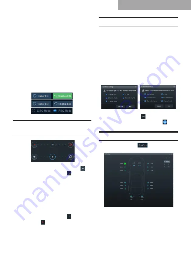
Setting the Channel Link
Link: The input link settings include Channel
EQ, X-Over, Channel Mute, Channel Phase and
Channel Volume; the output link settings include
Channel EQ, X-Over, Channel Mute, Channel
Phase, Channel Volume, and Channel Delay.
1. Link setting box:
(1) Set the input or output functions to be
tuned in the interface;
(2) Right-click the link settings in the input
channel area, the input link setting box
appears; right-click the link settings in
the output channel area, the output link
setting box appears.
2. Link setting:
Click the Link button “ ”, the Link button
is highlighted (the icon turns blue);
indicates that it is in the link state.
Setting the Delay
Click the Delay button “
”, the output signal
delay adjustment interface appears.
1. Delay unit: ms, cm, in;
Delay range: 0.000-20.000 ms;
0-692 cm;
0-273 in.
2. The delay can be set by directly entering
the value, scrolling the mouse wheel,
or pressing the Up/Down keys on the
keyboard.
Software for PC


