background image

3

DO NOT INSTALL THE MONITOR NEAR THE

PASSENGER SEAT AIR BAG.

If the unit is not installed correctly the air bag may not

function correctly and when triggered the air bag may

cause the monitor to spring upwards causing an

accident and injuries.

MAKE THE CORRECT CONNECTIONS.

Failure to make the proper connections may result in

fire or product damage.

Precautions

IMPORTANT

Please record the serial number of your unit in the

space provided on the back cover of Owner’s

Manual and keep it as a permanent record. The

serial number plate is located on the bottom of the

unit.

• For installation of the main unit, avoid areas with a

high incidence of dust or moisture. Installing the

unit in such locations may result in contamination

of the DVD ROM making it unreadable.

• Do not install the navigation system near a CD

player that may interfere with GPS signal recep-

tion.

• The optimum locations for installing the GPS

antenna are:

– on the dashboard where no metal piece (such as

the defogger wire or antenna wire) is located on

the windshield.

– where no metal cover is located.

• Route the Speed Pulse Sensor cable away from

the audio cables in order to avoid picking up

noises.

Caution

HAVE THE WIRING AND INSTALLATION DONE

BY EXPERTS.

The wiring and installation of this unit requires

special technical skill and experience. To ensure

safety, always contact the dealer where you pur-

chased this product to have the work done.

USE SPECIFIED ACCESSORY PARTS AND

INSTALL THEM SECURELY.

Be sure to use only the specified accessory parts.

Use of other than designated parts may damage this

unit internally or may not securely install the unit in

place. This may cause parts to become loose

resulting in hazards or product failure.

DO NOT INSTALL IN LOCATIONS WITH HIGH

MOISTURE OR DUST.

Avoid installing the unit in locations with high inci-

dence of moisture or dust. Moisture or dust that

penetrates into this unit may result in product failure.

ARRANGE THE WIRING SO IT IS NOT CRIMPED

OR PINCHED BY A SHARP METAL EDGE.

Route the cables and wiring away from moving parts

(like the seat rails) or sharp or pointed edges. This

will prevent crimping and damage to the wiring. If

wiring passes through a hole in metal, use a rubber

grommet to prevent the wire’s insulation from being

cut by the metal edge of the hole.

Содержание NVE-N852A

Страница 1: ...zano Sul Naviglio MI Italy Tel 02 48 47 81 ALPINE ELECTRONICS FRANCE S A R L RCS PONTOISE B 338 101 280 98 Rue De La Belle Etoile Z I Paris Nord Il B P 50016 F 95945 Roissy Charles De Gaulle Cedex Fra...

Страница 2: ...brake pedals etc can be extremely hazardous DO NOT SPLICE INTO ELECTRICAL CABLES Never cut away cable insulation to supply power to other equipment Doing so will exceed the current carrying capacity o...

Страница 3: ...tal cover is located Route the Speed Pulse Sensor cable away from the audio cables in order to avoid picking up noises Caution HAVE THE WIRING AND INSTALLATION DONE BY EXPERTS The wiring and installat...

Страница 4: ...t of silicone or some double stick tape applied to the bottom of the antenna This will prevent the magnetic base from moving and possibly scratching the paint on the vehicle Before Installing the Syst...

Страница 5: ...his process with checking the tachometer wire The tach wire increases voltage with the engine s RPM The speed pulse wire increases voltage with the vehicle s actual speed If any of these condi tions d...

Страница 6: ...itself If the vehicle icon does not move smoothly as you drive or the street name does not appear on the bottom of the screen you may not have the proper VSS wire Double check your connections and ver...

Страница 7: ...he roof Clean dust and oil at the mounting location and mount the antenna Notes The magnet of the antenna is very strong Proceed cautiously to prevent any damage to the vehicle s body Keep the magnet...

Страница 8: ...control computer etc in this case contents of the computer memory may be erased when the battery lead is disconnected Water proof pad 6 1 Connect the power lead to this unit Insert until a click sound...

Страница 9: ...parking brake signal line Connect to a metal part of chassis body with screw To the vehicle speed pulse line Use this to connect a device having the IN INT function Use this to connect a device having...

Страница 10: ...adhesive on the Velcro strips Press the Navigation unit onto the mounting location Continued to 5 Securing leads etc a When mounting on the rear tray Mount the brackets 1 on the unit Mount the bracket...

Страница 11: ...the floor with flanged self tapping screws M5 15 5 and spring washers M6 6 Warning Do not damage pipe or wiring when drilling holes Continued to 5 Securing leads etc 5 6 a When mounting with floor ba...

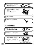
Страница 12: ...he engine key Make sure the unit is operating correctly by referring to the Owner s Manual ON Make sure all factory components such as brake lamps parking lamps etc work correctly a Remote control hol...

Страница 13: ...13...

Страница 14: ...14...

Страница 15: ...15...

Отзывы: