background image

072-0500


Alphasense User Manual


OPC-R1 Optical Particle Counter                    

Issue 1


Alphasense Ltd 

Page 17 of 33


February 2019


Sensor Technology House, 300 Avenue West, Skyline 120, Great Notley. Essex.CM77 7AA. UK 

Tel: +44 (0) 1376 556700    -   Fax: +44 (0) 1376 335899 

Email: [email protected]    -   Web: www.alphasense.com


Appendix B: Installing the device driver (drivers unchanged from OPC-
N2) 


Windows XP 

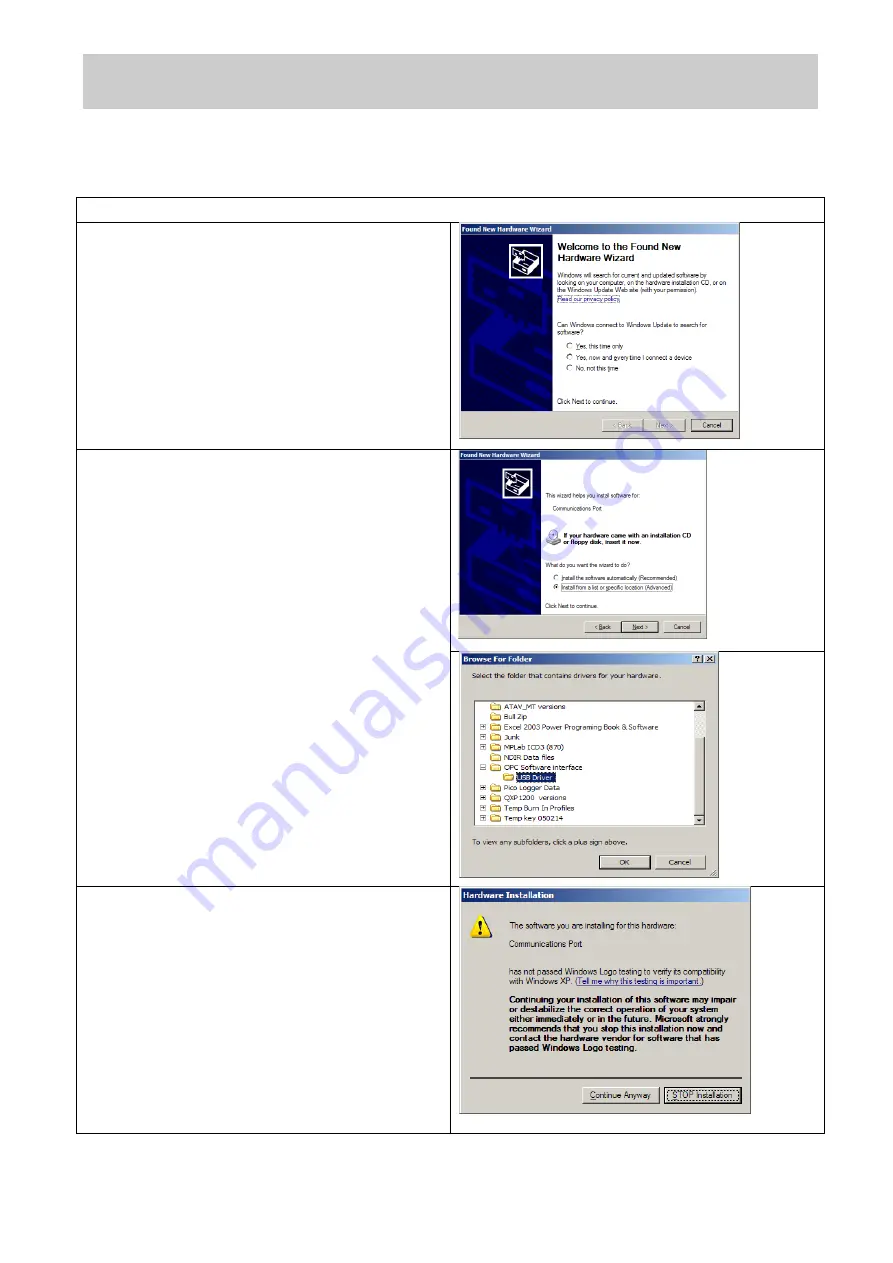
Copy the folder 

“OPC Interface Software” to the 

PC desktop.  Connect the USB interface lead to 
the  PC.    If  the  USB  interface  lead  (USB  to  SPI 
converter)  is  connected  to  the  PC  for  the  first 
time, Windows will need a device driver and this 
will start the 

“Found New Hardware” wizard. 

Select the 

“Yes, this time only” option and click 

next. 


The following window will give you an option as 
to  whether  to  use  a  CD  to  install  the  device 
driver or to use another location.  Select 

“Install 

from a list or a specific location (Advanced)

”. 

Navigate to the OPC folder containing the folder 
named 

“USB  Driver”,  this  contains  the  file 

devtech2.inf 

needed to drive the OPC device. 


Click OK to allow Windows to locate and install 
the device driver.  This process is automatic but 
you will be prompted by the form below to 
confirm the installation. 
Click 

“Continue Anyway” to finish the installation. 

Once the device driver is installed correctly, the 
OPC  device  should  appear  in  the  Device 
Manager  window  as  a 

“Communication  Port” 

with  an  assigned  COM  port  number.    Make  a 
note  of  this  assigned  port  number,  as  you  will 
need it when starting the software. 
 
The Driver installation is now complete.


Содержание OPC-R1

Страница 1: ...on 3 Health and Safety and Regulatory Information 4 How the OPC R1 works 5 PM Measurement 6 Sampling the environment Connecting and running the OPC 7 Connecting Power and Taking Readings 8 Running the...

Страница 2: ...e Initially a full deployment package will have been provided with the OPC R1 In the future this will be available via the web site or through contact with Alphasense Full instructions for carrying ou...

Страница 3: ...of software bins 16 Sampling interval seconds Histogram period recommended 1 to 30 Sample flow rate mL min 240 Max particle count rate Particles second 10 000 Detection limits PM10 Minimum Maximum el...

Страница 4: ...particle size spectra and concentration data assuming a particle density and refractive index RI Default settings weighting index 2 are density 1 65 g ml RI 1 5 i0 Respiratory profiles are included i...

Страница 5: ...le the smallest carbon particles will have a higher density than larger aggregates of the same particles different Particle Density values may be set for different bins to achieve a more accurate dete...

Страница 6: ...this must be ordered separately The green LED shows that power is supplied to the OPC R1 and the red LED flashes when the PC and OPC R1 are communicating SPI Connection The SPI socket is a Molex Pico...

Страница 7: ...eir own risk 9 The SS connection to the OPC should be driven LOW during any SPI communication with the OPC OPC SPI Commands A full list of current SPI commands given in 072 0501 Supplemental SPI infor...

Страница 8: ...king the laser and fan boxes turns the lasers and fan on Note that changing the laser power will alter the unit s response and will put the unit out of calibration Fan speed cannot be varied on the OP...

Страница 9: ...y are also given Reject Glitch and RejectLong TOF are an indication of the electronic noise and errors in timing respectively High values would suggest a problem with the unit or the set up The total...

Страница 10: ...ion vs Particle Size display mode Click the Histogram ml button on the left hand side of the screen to show the recorded data in particle number concentration particles per millilitre of sampled air f...

Страница 11: ...Web www alphasense com History Plot of Mass Concentration display mode Click the Histogram plot mass conc Button on the left hand side of the screen to show a temporal record of PM1 PM2 5 and PM10 val...

Страница 12: ...settings through the OPC software 1 Ctrl R Read and display all configuration variables This will display the variables available to the user for edit The data is displayed in the information window t...

Страница 13: ...Particle Counter Issue 1 Alphasense Ltd Page 13 of 33 February 2019 Sensor Technology House 300 Avenue West Skyline 120 Great Notley Essex CM77 7AA UK Tel 44 0 1376 556700 Fax 44 0 1376 335899 Email...

Страница 14: ...icle diameter um 0 55 0 9 1 3 1 7 12 2 Vol of a particle in bin um3 0 087 0 382 1 150 2 572 950 8 Weighting for bin 1 65 1 65 1 65 1 65 1 65 Individual bin weighting Data OADate Time Bin00 Bin15 Mean...

Страница 15: ...system to control the device and gather data A flow chart outlining simple operation of the OPC R1 is given in 072 0501 Supplemental SPI information for OPC R1 The R1 has a very low power off state u...

Страница 16: ...pected to fall to below 10 C the system should be heated or well insulated to ensure correct operation of the OPC How are the units calibrated The units are calibrated for sizing using controlled aero...

Страница 17: ...this time only option and click next The following window will give you an option as to whether to use a CD to install the device driver or to use another location Select Install from a list or a spe...

Страница 18: ...ail sensors alphasense com Web www alphasense com Windows 7 Copy the folder OPC Interface Software to the PC desktop Connect the USB interface lead to the PC If the USB interface lead USB to SPI conve...

Страница 19: ...e 120 Great Notley Essex CM77 7AA UK Tel 44 0 1376 556700 Fax 44 0 1376 335899 Email sensors alphasense com Web www alphasense com Right click the icon and select Update Driver Software Select the Bro...

Страница 20: ...elect the Install this driver software anyway option Windows will then install the driver files for the device Once the device driver software has been installed the form below will be displayed Make...

Страница 21: ...s include an electronic fingerprint that indicates which company produced the driver as well as an indication as to whether the driver has been modified since the company released it This increases se...

Страница 22: ...Tel 44 0 1376 556700 Fax 44 0 1376 335899 Email sensors alphasense com Web www alphasense com Then click on the Recovery option on the left hand side Once selected you will see an advanced startup se...

Страница 23: ...oot time configuration settings you will need to restart your Computer one last time Finally you will be given a list of startup settings that you can change The one we are looking for is Disable driv...

Страница 24: ...com Web www alphasense com To disable the signature verification it is necessary to get into Troubleshooting options from the boot manager Select Restart from the power options menu for Windows 8 thi...

Страница 25: ...nce we are modifying boot time configuration settings you will need to restart your Computer one last time Finally you will be given a list of startup settings that you can change The one we are looki...

Страница 26: ...the laser setting and ToF to SFR factor before updating the firmware as this may be reset to default once updated To upgrade the firmware on your OPC R1 device requires Bootloader tool Alphasense USB...

Страница 27: ...ands OPC R1 SPI functions from point of view of SPI Master system for firmware versions 2 01 2 21 Function Command byte Byte s out Byte s in 0xF3 is set as standard initial return byte value from OPC...

Страница 28: ...0x3F InfoStr ascii char07 F 0x46 0x3F InfoStr ascii char08 i 0x69 0x3F InfoStr ascii char09 r 0x72 0x3F InfoStr ascii char10 m 0x6D 0x3F InfoStr ascii char11 w 0x77 0x3F InfoStr ascii char12 a 0x61 0x...

Страница 29: ...at 10 ms be used as delay between command byte and following byte 0x12 0xF3 0x12 FirmwareVerMajor FirmwareVerMajor is unsigned 8bit integer variable 0x12 FirmwareVerMinor FirmwareVerMinor is unsigned...

Страница 30: ...te0 Sampling Period is a float variable occupying 4 bytes and is a 0x30 Sampling Period Byte1 measure of the histogram s actual sampling period in seconds 0x30 Sampling Period Byte2 0x30 Sampling Peri...

Страница 31: ...cupying 4 bytes Units are ug m3 0x32 PM_B Byte1 0x32 PM_B Byte2 0x32 PM_B Byte3 0x32 PM_C Byte0 PM_C is a float variable occupying 4 bytes Units are ug m3 0x32 PM_C Byte1 0x32 PM_C Byte2 0x32 PM_C Byt...

Страница 32: ...iginal command byte value sent for the command to be validated by the OPC R1 If it is not the OPC R1 will load the SPI buffer with 0x31 busy value and return to its normal mode of operation THE SAMPLI...

Страница 33: ...ation is a 16 bit method similar to that used in MODBUS communication It uses the generator polynomial value 0xA001 and is initialised to 0xFFFF Example C programming code showing how the checksum can...

Отзывы: