


19
We reserve the right to modify technical specifications without prior notice.
UK830304/190326
© Alpha-InnoTec GmbH
Installation of the control
element
DANGER!
Danger of fatal injury due to electric
shock!
Electrical connections may be installed
only by qualified electricians.
Before opening the unit, disconnect the
system from the power supply and secure
it from being switched back on!
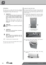
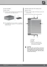
Situated at different heights in the front panel of the unit
are four-pin sockets for fastening the control element:
1 four upper recesses
2 four lower recesses
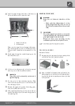
Four hooks are located on the back side of the control
element and can be used to hang the control element on
the front facade of the unit:
If such a connection is desired, lay a
category 6 screened network cable with
RJ-45 plug through the unit parallel to the
heating and heat pump regulator control
cable already present when making the
connections, and lead it through the front
panel of the unit.
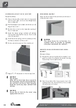
Close electrical switch cabinet of unit....
Attach the lower facing panels.
Flushing, filling and bleeding
the system
Flush, fill and bleed the heating circuit...
In addition, bleed the condenser of the heat pump...
t
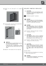
Open the lower facing panel...
t
Open the bleed valve...
Following bleeding, close the lower facing panel.
Insulating the hydraulic
connections
Insulate the vibration decouplers and the pipes of the
heating circuit.
NOTICE.
Insulate in accordance with applicable
local standards and directives.


